Continue to Site

Eng-Tips is the largest engineering community on the Internet

Intelligent Work Forums for Engineering Professionals

  • Congratulations cowski on being selected by the Eng-Tips community for having the most helpful posts in the forums last week. Way to Go!

Over dimensioning around center lines 3

Status
Not open for further replies.

Oaklandishh

Mechanical
Sep 3, 2014
48
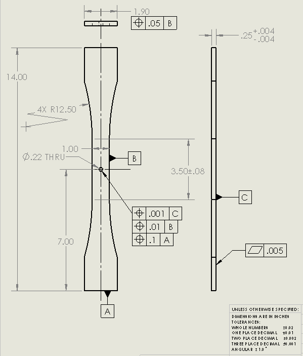
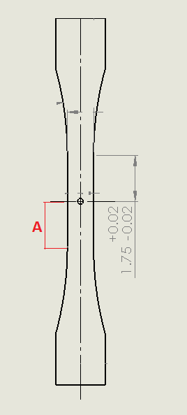
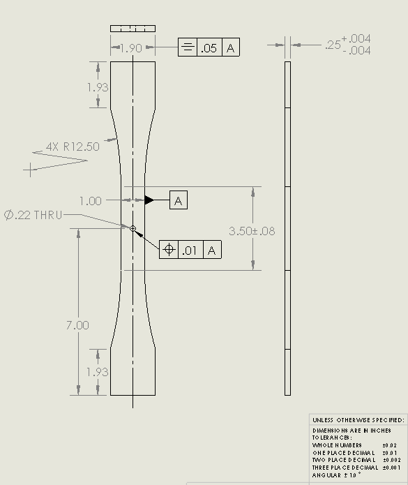
I have a part with a symmetric line down the middle as shown in attached picture.

Assuming I am using current ASME standards, having the dimension labeled 1(red) and the dimensions 2 and 3 would be over constraining the part correct?

Is having only the dimension labeled 1 and not having dimensions 2 and 3 an acceptable way to dimension the part?

What about having only dimensions 2 and 3 and not 1, similar to how dimension 4 is being used?

As a semi related bonus question, if I put in a center line, does that imply the part is supposed to be symmetrical about that line in all views or just in the view with the center line? Can I use a center line on a part that is not completely symmetrical about that axis in the given view as long as the non symmetrical features are obvious?

I have tried looking these up, but I cant find exactly what I want in ASME Y14.5 or a good example on google, sorry if this is obvious and I have just missed it.


 http://files.engineering.com/getfile.aspx?folder=396539a4-04ba-4943-aec6-ae9d0d779e2a&file=CenterlineOverConstrained.png
Replies continue below

Recommended for you

Oaklandishh,

Your centreline indicates symmetry. You need a width dimension for the narrow part. You don't need the half dimensions.

The block of [±][ ]tolerances does not work for a drawing like this. You have to select a feature that defines your centreline, then apply position tolerances to your widths, or apply profile tolerances.

--
JHG
 
I agree with drawoh. This is insufficient. A centerline does not exist without a feature. This looks like you believe a centerline exists and you're locating the part surfaces to it. It doesn't work like that. The answer to all of your questions is "no" except for this one:

if I put in a center line, does that imply the part is supposed to be symmetrical about that line in all views or just in the view with the center line?
.

The answer is "just in the view with the centerline." I can't imagine a scenario where features would be symmetrical in one view and asymmetrical in another though so maybe I don't understand your question. Be advised that an implied dimension does not equal an implied tolerance so yes you can imply that the features are symmetrical but you can not imply the tolerance. It has to be specifically stated.

John Acosta, GDTP Senior Level
Manufacturing Engineering Tech
SSG, U.S. Army
Taji, Iraq OIF II
 
OP, maybe take a look at section 2.7.3 of ASME Y14.5M-1994 (or equivalent in newer versions) to get a better understanding of why showing features aligned doesn't automatically imply that they actually are well aligned.

Posting guidelines faq731-376 (probably not aimed specifically at you)
What is Engineering anyway: faq1088-1484
 
Thanks,

These have been very helpful.

powerhound, when you say
powerhound said:
Be advised that an implied dimension does not equal an implied tolerance so yes you can imply that the features are symmetrical but you can not imply the tolerance. It has to be specifically stated.
this means that as in the photo below, the 1.75" dimension is implied at location A, but the +-.02" tolerance is not? So if I wanted both dimension and tolerance I would have to put both dimensions in?

UpdatedExampleDrawings_et39fu.png
 
Not exactly. Without the use of datum reference frames, there's no way to tell what the hole is centered on. The dimension you've shown cannot be reliably and repeatably verified. To be clear, the implication of symmetry only happens when the GD&T standard is called out on the print. That being said, you can't just put it on this print and think the problem is solved because of the things on here that violate that standard.

Why don't you take a stab at controlling these features using GD&T and put it on here? This way we can see where you are GD&T wise and instead of just telling you what to do, we can guide you.

John Acosta, GDTP Senior Level
Manufacturing Engineering Tech
SSG, U.S. Army
Taji, Iraq OIF II
 
What if the hole was not there and I was dimensioning the start of the radii?

1.75 +-.02 coming from a center line wouldn't imply a tolerance of 3.5+-.04 of the flat section?

Here is my attempt of using GDT to dimension the part, I don't have much background in this so this is pretty much what I can piece together from misc internet sites.

GDTAttempt_jooiji.png


Thanks for your help so far.
 
Now we're talking :)

It's still incomplete but what you've done is a good start.

I'll go over this a little at a time. Your positional callout may need a diameter symbol before the tolerance value but it depends on function. Let's assume you just left it off by accident. Next, all you are controlling with this callout is how centered the axis of the hole is to the width of datum feature A. It can be as slanted as it wants to be along the vertical axis. What you probably want is for the hole to be perpendicular to the bottom surface. You also want it to be centered in the length. You can either make one end datum feature C or make the centerplane of the length. So if you make the bottom surface datum feature B and one end or the centerplane of the length datum feature C, you can change the feature control frame on the hole to B|A|C. This says that teh hole must be perpendicular to B, centered on A and centered on C.

Give that a shot.

John Acosta, GDTP Senior Level
Manufacturing Engineering Tech
SSG, U.S. Army
Taji, Iraq OIF II
 
Oaklandishh,

I largely agree with Powerhound. If this were my drawing, the bottom face would be datum[ ]A, your 1.00[ ]dimension would be datum[ ]B and the end your dimensions are from would be datum[ ]C. Don't think of datums as something you dimension from. Datums tell your fabricators and inspectors how to fixture your part. This should reflect how you intend to use the part, and you should dimension from datums, but datums are a fixturing specification.

You used a symmetry control on your 1.90[ ]dimension at one end. I have no idea of why anyone would use symmetry in GD&T. This is the closest thing I have seen to an intelligent use of it. I think a positional tolerance is a better way to locate a feature of size.

Your 1.00[ ]dimension, used to define your datum, is [±].002, based on your title block. Features Of Size (FOS) are valid datums, but you need to be careful. If you specify the FOS at maximum material boundary (MMB), it is easy to make inspection tooling, but it may be a rotten functional idea. If you do not specify MMB, it takes some fiddling around to figure out where your centre is. Again, your datum is a fixturing specification. I figure that if my FOS[ ]datum is ten times more accurate than the tolerances I am applying, I have no problem.

--
JHG
 
Powerhound,

Thanks for taking the time to walk me through this, I am trying to get a better hand on GD&T and your comments are very helpful.

If I want different tolerances in the vertical, perpendicular, and horizontal dimensions am I allowed to have two or more true position feature control boxes on the hole?

Also wouldn't the holes diameter tolerances constrain it's perpendicularity to the bottom surface as a tilted hole increases in one diameter the more it is tilted?

 
Drawoh,

I think I understand what you are saying about the datums.

I am not sure how I would implement the same effect as the symmetry using a positional tolerance. Would just replacing the symmetry symbol with the true position symbol imply it was a true position from the center-line defined by the current 'A'?

as for the last part, I am pretty sure I don't want a MMC call out, but I also think that the ease of inspection you have talked about is lost on me.

Thanks for the response.

 
If I want different tolerances in the vertical, perpendicular, and horizontal dimensions am I allowed to have two or more true position feature control boxes on the hole?

Keeping in mind that the perpendicular tolerance zone is only controlling perpendicularity, not location, you can have two different feature control frames if you want more tolerance in one direction than the other. In this case you would leave the diameter symbol off of teh feature control frame.

Also wouldn't the holes diameter tolerances constrain it's perpendicularity to the bottom surface as a tilted hole increases in one diameter the more it is tilted?

No. I also don't see what you mean when you say the hole diameter increases as it's tilted.

John Acosta, GDTP Senior Level
Manufacturing Engineering Tech
SSG, U.S. Army
Taji, Iraq OIF II
 
I didn't mention the issue of using symmetry because while it is undesirable, it's not incorrect to use. I was just sticking with the fundamental issues of the print.

John Acosta, GDTP Senior Level
Manufacturing Engineering Tech
SSG, U.S. Army
Taji, Iraq OIF II
 
Powerhound,

see picture for hole diameter. the more the cutter is tilted the more the d+e diameter changes. at some angle, the hole diameter will automatically be out of spec correct?

angledhole_vphuha.png


so as the drawing is currently, the part can very .01" from the center line and .004" from the base. adding the diameter call out doesn't make sense unless there are two datums to define the tolerance circles center or am I misunderstanding the use of the diameter symbol here.

sorry I have so many questions. I have been doing a bunch of reading, but it usually is hard to grasp without specific examples.
 
I see what you're saying but that's not how size is defined per ASME. The size of this hole will be defined by two point measurements normal to the axis of the feature. This is what is called Actual Local Size. The feature can have many different local sizes but the measurements are always normal to teh axis so measuring the elliptical dimension is not a valid measurement of size. Just think of the largest pin you can get through the hole without a hammer. That is what would be referred to as the Unrelated Actual Mating Envelope (UAME). If you were to locate this hole with respect to the bottom surface as the primary datum feature, it would ensure that the axis of the hole would be perpendicular to that surface within the tolerance zone. The diameter symbol in the feature control frame is what indicates the shape of the tolerance zone. It means it is cylindrical.

John Acosta, GDTP Senior Level
Manufacturing Engineering Tech
SSG, U.S. Army
Taji, Iraq OIF II
 
Thanks for the heads up.

I have made some changes based on what I think you guys have been telling me, although I am not sure I removed the symmetry call out correctly.

My intent was to make their center lines offset by at max .05"?

GDTUpdate2_tbw7rm.png


Hole should be perpendicular to a thou, centered horizontally to a hundredth and vertically to a tenth?
 
Oaklandishh,

The attached file shows how I interpret your symmetry specification, or at leasty, shows an example of what would meet the specified requirement. Note how I have exaggerated your tolerances. Symmetry would refine a dimension or profile tolerance. Presumably, the symmetry tolerance would be more accurate than the other tolerances. I have no idea why anyone would do this.

--
JHG
 
 http://files.engineering.com/getfile.aspx?folder=fbe17c50-3a3b-43e9-a047-aa96f946c1fd&file=P1030182.JPG
I think that this works for my case, but it would be more difficult to QC the parts.

What is the preferred way to control the center of the tabs to be relative to the center of the neck? Is using true position as I did in the updated version reasonable?

Thanks for the picture.
 
I know this is completely off topic to your original question but something really jumped out me that I thought might be worth your consideration.

Your stated tolerances unless otherwise noted:
Code:
Whole numbers: +/-.02
One Place Decimal: +/- .01
Two Place Decimal: +/- .002
Three Place Decimal: +/- .001

It's rather... unorthodox, I suppose. Especially your tolerance on two-place decimal numbers. Your hole size brought it up in my mind. I found it strange that you would apply a .001 perpendicularity control on a two-place diameter, and that's when I noticed how tight your default tolerances were on it. Is the as-modeled diameter even between .218 and .222?

Just throwing that out there. I apologize if this tangential topic is unwanted.

_________________________________________
NX8.0, Solidworks 2014, AutoCAD, Enovia V5
 
The normal default tolerances are
Code:
Whole numbers: +/-.02
One Place Decimal: +/- .01
Two Place Decimal: +/- .005
Three Place Decimal: +/- .001
I must have messed up my template at some point.

Also the hole is just dimensioned for completeness the actual tolerance I want on the diameter is +-.0005"
 
Status
Not open for further replies.

Part and Inventory Search

Sponsor