Continue to Site

Eng-Tips is the largest engineering community on the Internet

Intelligent Work Forums for Engineering Professionals

  • Congratulations waross on being selected by the Eng-Tips community for having the most helpful posts in the forums last week. Way to Go!

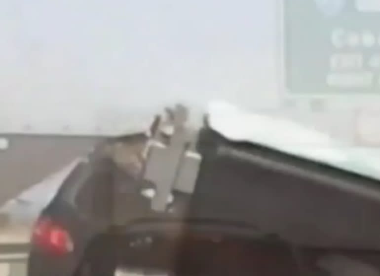
Overhead sign crushes car on freeway in Melbourne Australia. 3

Status
Not open for further replies.

MDEAus

Mechanical
Mar 21, 2018
44
This happened a few days ago, but the article has just been updated with dash-cam footage from the car immediately behind the one involved.
very quickly it can be seen that the failure point is at the welded joint for the bolted connection. the grainy footage makes things harder to see, the base off the standoff looks weird, why would you close the end off the SHS to be welded to the main beam? Galvanising requires drainage points and a minimum area open between closed sections. Unless that is a solid block off steel? I'm not sure why they would have used a solid block off steel though.

 
Replies continue below

Recommended for you

It should have been designed for infinite fatigue life for natural wind gust loading, and perhaps for truck-induced gust loading as well. Whether that particular connection was or wasn't is still speculation at this point, but since it's in Australia, it's unlikely it was to the AASHTO criteria. I can't imagine the Australian code is substantially different, though.
 
Interesting that it tore out two neat squares. I wouldn't have guessed that.
 
HotRod10 said:
- one engineer designs the box section to span the roadway while another engineer designs the sign supports, and each assumes the other (or someone else) checked the connection between them.
Maybe, but I think it's probably likely that the connection was detailed somewhere, and through someone's oversight never got implemented when the sign was assembled. But, maybe not.

Brad Waybright

It's all okay as long as it's okay.
 
IRstuff, even with a perfect weld, small out-of-plane bending stresses on the base metal will result in fatigue. Given the size of the base relative to the size of the sign, the top plate of the gantry would have seen significant stress every time a truck passed under the sign. It was doomed to fail regardless of the quality of the welds.
 
Tomfh,

Neither would I have guessed that. Thus my guess above that the holes were made first, and the tube was inserted and welded in place. If we had a better resolution picture of the bottom of the upright, that could be determined. There does appear to be a shadow around the perimeter indicating that the walls of the tube extended below the plate.
 
Hokie66,

Plug welded it? Interesting.

I hope we get some good close ups.
 
No, I think all the welding was just fillet welds. May have been intended to be full penetration, but that is not what happened. Yes, some close ups are needed, along with thicknesses of the gantry horizontal and size of the tube.
 
Hokie66,

If the stub post was inserted into the gantry beam a short distance(on the scale of 10-20mm), what would explain the capped end? It would seem unnecessary as the flange would cap the stub post.

The shadows around the perimeter would be deformed metal as it tore away.

A new story about it but no new information just the best guesses (same as this thread, especially my input)of engineering professors.

 
Hokie66, I meant the column stub "plugged" into a hole in the gantry tube.
 
steveh49 said:
AASHTO is poorly written IMO. Clause 5.6.2 does appear to outlaw SHS/RHS but then rules are provided for them, however there is nothing provided for them in terms of fatigue (aside from the impractical FEM requirements). I wouldn't be surprised if designers are getting it wrong.

For those of us who do not have this standard would it be possible to post the words from clause 5.6.2?

Thanks
 
This photo suggests the base plate was part of the gantry fabrication, while the foot of the sign was part of the sign fabrication. The two mated at the jobsite and the gantry fabricator not making any great consideration or calculation for the demands of the signage attached. All those thick plates and bolts, secured with a zip-loc baggie weld.

sign_pedestal_q8om7q.jpg
 
Nice angle.

To me the whole assembly here looks to be related and is part of the sign fabrication. The paint, plate sizes, plate thicknesses, bolt pattern, and HSS size are all matched. The motivation also makes sense because this assembly would allow the sign installers to locate and weld the base to the gantry on one day with nothing but a man lift. Then they could come back and quickly bolt up the sign on another day to minimize heavy crane time.
 
Charliealphabravo

I guarantee that the stub posts were welded on before the gantry was transported and installed, they use the stub post for easier transport. Easier to transport something long and skinny then something long with 5m branches off the side.

Epoxybot

As I've said earlier the video shows it wasn't the welds that failed in this case. However they may have contributed to the lack of fatigue strength in the base material. The investigation needs to uncover how and why the fatigue strength was so low, and how it was approved as such.

If that SHS post is 200mm square then those flanges are at least 20mm thick each and since (in my opinion) the gantry tore out around the weld (weld survived intact )the gantry can't have been constructed from greater than 6mm plate (judging from the grainy pictures based on relative size of what is still attached to the base of the stub post).
 
MDEAus said:
If that SHS post is 200mm square then those flanges are at least 20mm thick each and since (in my opinion) the gantry tore out around the weld (weld survived intact )the gantry can't have been constructed from greater than 6mm plate (judging from the grainy pictures based on relative size of what is still attached to the base of the stub post).
Great
I concur with the estimation of max 6mm plate (possibly thinner) and 200SHS.
 
Failure of the base metal adjacent to a weld is typical of a fatigue failure. The allowable fatigue stress on the base metal at a fillet welded connection subjected to out-of-plane bending, as the top plate of the gantry would have been, is very low - 2.6ksi under the AASHTO (American) code. Since Australian steel is not substantially different than American steel, it's probably about the same. Given the 5m height of the cantilevered sign, it would not take much wind pressure to exceed that stress, even if the plate is 20mm thick.
 
So are there 3 bad gantries or 3 good gantries out of 17?

Transurban's David Clements said an audit had found two other signs on the network were also missing the component, and have since been removed.

"There are 17 gantries that have similar signs supported in this manner, and of those 17 there are only three that have the stiffener plate required in the detailed design," he said.


----------------------------------------

The Help for this program was created in Windows Help format, which depends on a feature that isn't included in this version of Windows.
 
I was confused by those sentences too. It sounds like only 3 have the required stiffener plate. Some contractor is going to be in hot water.
 
Status
Not open for further replies.

Part and Inventory Search

Sponsor