Continue to Site

Eng-Tips is the largest engineering community on the Internet

Intelligent Work Forums for Engineering Professionals

  • Congratulations KootK on being selected by the Eng-Tips community for having the most helpful posts in the forums last week. Way to Go!

Partial Steel Beam Reinforcement Anchor Force 7

Status
Not open for further replies.

Baffled Engineer

Structural
Jul 27, 2018
56
Hello,

I'm working on a steel beam reinforcement consisting of a new W-shaped beam welded below an existing W-shaped girder, which looks like this:
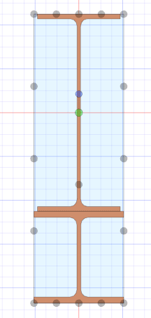
Girder_Reinforcement_xihayd.png


I'm trying to determine the anchorage force and extension required for partial reinforcement. According to my reference below from the Canadian Steel Handbook, the formula provided consist of the area of the reinforcement times the distance from the centroid of the reinforcement to the centroid of the entire combined section, which is the same variable (Q) used in shear flow calculations. My question is, would this formula still apply to my W-shaped reinforcement? Or is it limited to cover plates?

I'm concerned that there's an implicit assumption that the plate has uniform stress if assumed to be thin, and with the W-shaped reinforcement, there is a considerable stress distribution across the depth of the section. Any thoughts on this? Thanks.
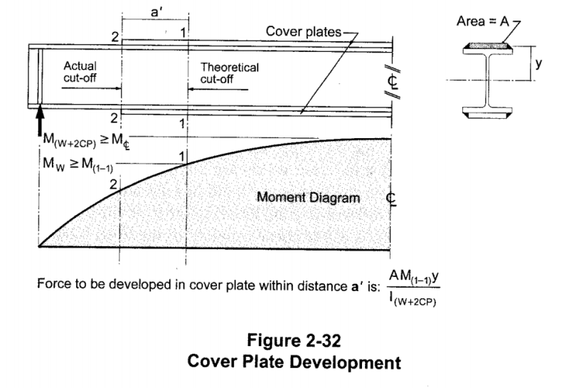
Reinforcement_Development_ttgl9i.png
 
Replies continue below

Recommended for you

Shear flow is VQ/I. It is not limited to cover plates.

BA
 
BAretired said:
Shear flow is VQ/I. It is not limited to cover plates.

Thanks for the reply.

I agree shear flow is not limited to cover plates and yes it's VQ/I, but the anchorage force formula provided in my reference is MQ/I.

Do you think there is still no difference and the anchorage force formula is also applicable to W-shaped reinforcements considering that the cover plate is a relatively flat element, and the W-shaped reinforcement has depth in it?
 
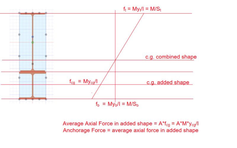
The anchorage force is equal to the total axial force in the reinforcing member, MQ/I. See below.

image_bnff36.png


BA
 
Baffled_Engineer said:
Do you think there is still no difference and the anchorage force formula is also applicable to W-shaped reinforcements considering that the cover plate is a relatively flat element, and the W-shaped reinforcement has depth in it?

I feel that your instincts with that are sound. My understanding is that the final deformation state in the reinforcement member may be viewed as having two components:

1) Transverse load inducing a reinforcement member centroidal curvature matching that of the composite member. This generates a vertical force demand at the connection which VQ/IT does not cover and;

2) Axial load inducing a reinforcement centroidal stretching that has the effect of offsetting the centroidal curvature to larger radii, thus producing true composite action. This leads to a shear slip tendency which creates a horizontal force demand in the welds and for which we do the VQ/It.

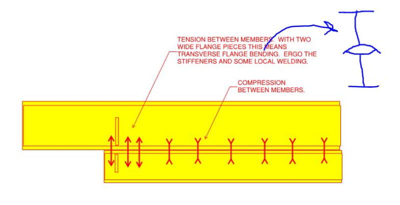
The weld demand described in #1 is insignificant for reinforcing members with small moments of inertia. With increasing moments of inertia, however, the effect becomes more pronounced (it may still be insignificant relative to VQ/I though). For this reason, and for general stability, I feel that it is a good practice to install partial height stiffeners as shown below along with some concentrated, local welding at that location. That, in addition to the MQ/I stuff.

c01_xhg2p2.jpg
 
Does this help? Depends on your loading to determine the cut-off point, and I'd extend the section past the cut-off point. Modify the shear values to determine the intermittent weld. Check to see you are happy with the numbers.


Rather than think climate change and the corona virus as science, think of it as the wrath of God. Feel any better?

-Dik
 
 https://files.engineering.com/getfile.aspx?folder=ffb9d1f8-ee2f-485b-a787-aa33c1ca7a2e&file=Comp-W_W.pdf
I see no need for the stiffeners recommended by KootK. They accomplish nothing. Stress in the weld is parallel to the neutral axis of the section. Curvature of the added W section is a natural result of the eccentric axial load applied. There is no tendency for cross flange bending, unless perhaps from the heat of the weld, but I don't think that is what we are talking about.

The cut-off point is important, however. The added W section requires a certain distance to become fully effective. Axial stress at the end is zero.

BA
 
BART: Agree, but it is nice to see him using partial depth stiffeners...

Rather than think climate change and the corona virus as science, think of it as the wrath of God. Feel any better?

-Dik
 
BAretired said:
There is no tendency for cross flange bending...

dik said:
BART: Agree...

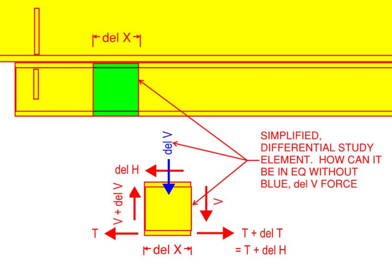
If you deny the existence of the force shown in blue below, then how would you put the differential element back into equilibrium with respect to vertical force? For convenience, I've pretended that all of the flexural tension resides in the lower flange. I don't believe that compromises the argument but, if I'm wrong, I'll be grateful to hear about it.

c01_vrwcm8.jpg
 
Upon further consideration, I believe KootK has a valid point. The lower beam carries a portion of the total shear. Since it does not extend to the support, it needs stiffeners to carry its reaction into the upper beam. In the absence of stiffeners, the reaction would need to be carried by flange bending.

BA

BA
 
I concurr... thanks, Koot...

Rather than think climate change and the corona virus as science, think of it as the wrath of God. Feel any better?

-Dik
 
There is a transition zone at both ends of the reinforcement beam where the section is not fully effective. There may be a tendency to bend the flanges within the transition zone, but, if the original beam is adequate to resist the maximum shear between support and reinforcement (which it must be or the reinforcement would continue to the end), then the addition of stiffeners at the ends of the lower beam does not contribute to the strength of the built up beam.

BA
 
BAretired said:
There may be a tendency to bend the flanges within the transition zone, but, if the original beam is adequate to resist the maximum shear between support and reinforcement (which it must be or the reinforcement would continue to the end), then the addition of stiffeners at the ends of the lower beam does not contribute to the strength of the built up beam.

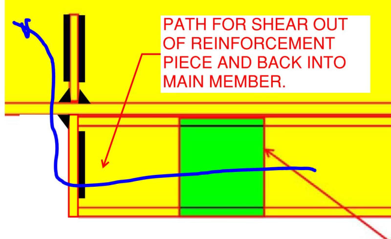
There needs to be shear in the reinforcement piece regardless of whether or not the original beam is adequate for shear on its own. And, since the shear in the reinforcement has to get in and out of that piece somehow, then I feel that the flange bending & weld tension issues exist regardless of the shear capacity of the original beam.

Do you know how to quantify the length of this "transition zone" such that its capacity can be evaluated? I don't other than to maybe ballpark it as 2X the depth of the reinforcing piece or something like that. Given that uncertainty, just throwing in a stiffener set to make sure that the issue is resolved convincingly seems entirely reasonable to me.

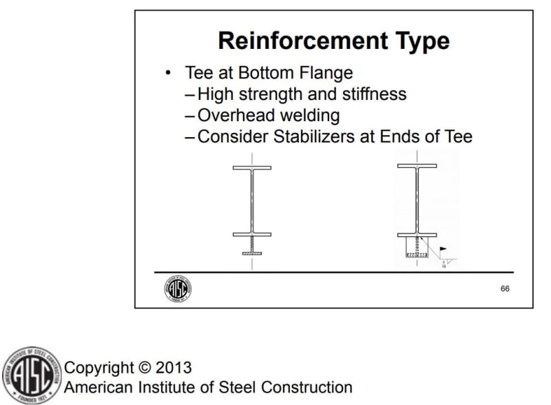
I typically throw in a stiffener to serve as a stabilizer as shown below, independent of the issue that we're discussing here and simply as a matter of good practice. The fact that the stiffener can also act to relieve cross flange bending is effectively just a negligible cost bonus.

c01_nhimin.jpg
 
To clarify for OP, if he's still around, this is really what I'd be aiming for.

c01_tyvwef.jpg
 
KootK said:
There needs to be shear in the reinforcement piece regardless of whether or not the original beam is adequate for shear on its own. And, since the shear in the reinforcement has to get in and out of that piece somehow, then I feel that the flange bending & weld tension issues exist regardless of the shear capacity of the original beam.

I am still in the process of thinking about it. I believe your model is wrong. Consider the reinforcement beam by itself. Apply an eccentric force to both ends of the beam, which is the horizontal weld shear. That is tantamount to a beam with an equal and opposite moment at each end. Shear throughout the span is zero.

That is where I am at the 'moment' (if you'll pardon the expression).

BA
 
BAretired said:
Consider the reinforcement beam by itself. Apply an eccentric force to both ends of the beam, which is the horizontal weld shear. That is tantamount to a beam with an equal and opposite moment at each end. Shear throughout the span is zero.

I've considered it:

1) The MQ/I welds at the ends of the reinforcing certainly feel like a concentrated moment in the way that you've suggested. However, the welds between the ends are normally introducing additional shear as well which implies a shear force that is varying along the length of the member. And that returns us to my differential element FBD.

2) In any normal built up beam, I feel that this logic chain applies:

a) One requires the new, low flange force to vary along the length of the beam.

b) [a] dictates that the reinforcing member horizontal shear increases along the length of the beam.

c) dictates that the reinforcing member vertical shear increases along the length of the beam since vertical and horizontal shear are everywhere and always complimentary.
 
The flange force will vary under constant shear. Varying shear isn't needed.

Regarding the del_V in the free body diagram, and assuming you're talking about a location away from the end of the reinforcement (away from the disturbed region), the balancing force is the external load that causes the del_V, or rather the portion of the external load that is supported by the reinforcement since del_V is defined over the reinforcement depth only. The welds need to transfer this if you don't assume direct bearing by the main beam on the reinforcement. I would design the welds for this.

The welds alternatively need to 'hang' a load if applied at the bottom flange.

In either case, the del_V load is presumably modest or you'd need stiffeners everywhere.

At the end of the reinforcement, del_V isn't only due to external load as already identified in the discussion above. I wonder though whether a single stiffener at the end of the reinforcement is enough. I think that a pair at say 2/3*D_reinf would be better but not sure if absolutely required. Or maybe the spacing should also relate to the flange width.
 
steve49h said:
Varying shear isn't needed.

It's needed if you want to be able to accommodate uniform loads and any moment diagram that isn't linear varying.

steve49h said:
In either case, the del_V load is presumably modest or you'd need stiffeners everywhere.

As I mentioned previously, I see it as being of potential significance where:

1) The reinforcing possesses a significant moment of inertia in its own right and;

2) Even then probably only at the ends where the reinforcement shear must migrate into the original member.

It's often a moot point between the ends because many beams of this sort will be loaded above the reinforcing member, putting the joint in compression as you mentioned. And, where loading would be at the bottom of the beam, it's hard to imagine designers forgetting to design the welds for direct tension.

steve49h said:
I think that a pair at say 2/3*D_reinf would be better but not sure if absolutely required.

Whether one wants additional stiffeners or not, I can't see much logic in omitting the stiffeners at the ends. Those stiffeners have awesomely direct load transfer from the reinforcing web straight into the existing beam web, sans flange bending. Stiffeners located anywhere else would involve some reliance on flange bending around the stiffeners and non-uniform stresses in the welds.
 
At long last, I now agree that KootK is correct. Under uniform load, horizontal shear from the flange welds causes the lower beam to curve upward (tension on top). But the beam curves downward, so some of the applied load is acting directly on the lower beam (through the upper beam). Reactions at each end must be transferred to the upper beam by stiffener plates.

BA
 
Status
Not open for further replies.

Part and Inventory Search

Sponsor