Continue to Site

Eng-Tips is the largest engineering community on the Internet

Intelligent Work Forums for Engineering Professionals

  • Congratulations KootK on being selected by the Eng-Tips community for having the most helpful posts in the forums last week. Way to Go!

Partial Steel Beam Reinforcement Anchor Force 7

Status
Not open for further replies.

Baffled Engineer

Structural
Jul 27, 2018
56
Hello,

I'm working on a steel beam reinforcement consisting of a new W-shaped beam welded below an existing W-shaped girder, which looks like this:
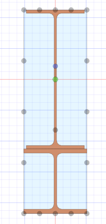
Girder_Reinforcement_xihayd.png


I'm trying to determine the anchorage force and extension required for partial reinforcement. According to my reference below from the Canadian Steel Handbook, the formula provided consist of the area of the reinforcement times the distance from the centroid of the reinforcement to the centroid of the entire combined section, which is the same variable (Q) used in shear flow calculations. My question is, would this formula still apply to my W-shaped reinforcement? Or is it limited to cover plates?

I'm concerned that there's an implicit assumption that the plate has uniform stress if assumed to be thin, and with the W-shaped reinforcement, there is a considerable stress distribution across the depth of the section. Any thoughts on this? Thanks.
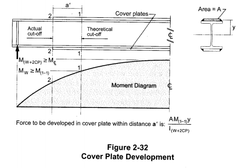
Reinforcement_Development_ttgl9i.png
 
Replies continue below

Recommended for you

You're welcome, dik, but I don't suppose this issue comes up very often. I can't remember ever strengthening a beam with anything other than a plate. Prior to seeing this thread, and given this problem, it would never have occurred to me to provide for a reaction at the end of the reinforcing beam.

BA
 
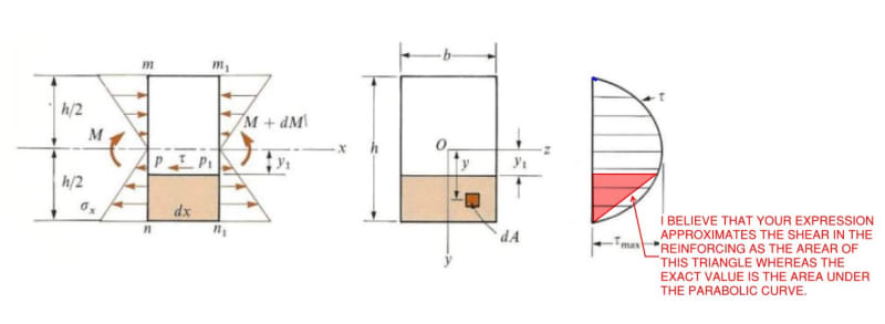
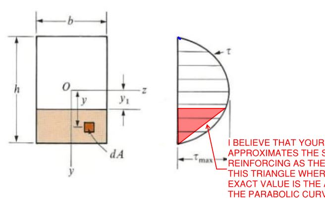
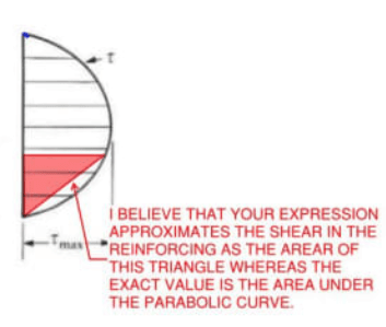
Thanks for the mathing BAret. I've done some modest verification on that and agree with your latest post, noting that the expression below is a linear approximation of what is actually a parabolic function. In some cases it would produce erroneous results but, in the particular case to which you've applied it, would produce a reasonably accurate, slight underestimate of the shear in the lower piece.

c02_td9750.jpg
 
I've always just added a plate on the end to stabilise the section (usually T)... i Don't recall the last time I did a W Section composite... the topic was great... Kudos to the Baffled guy...

Rather than think climate change and the corona virus as science, think of it as the wrath of God. Feel any better?

-Dik
 
@Koot... what is the parabolic function, if I may ask?

Rather than think climate change and the corona virus as science, think of it as the wrath of God. Feel any better?

-Dik
 
I haven't bothered to work out the details dik. I just know that it takes a parabolic form from mechanics of materials. My first step in checking BA's stuff was to reverse the roles of the main member and reinforcement to see if the total equaled 100% of the total shear. It was off by a significant margin. This is why. BA's approximation is more applicable to some cases than others. Which is fine, of course, as that's usually the way of things with approximation.

c02_ds6avk.jpg
 
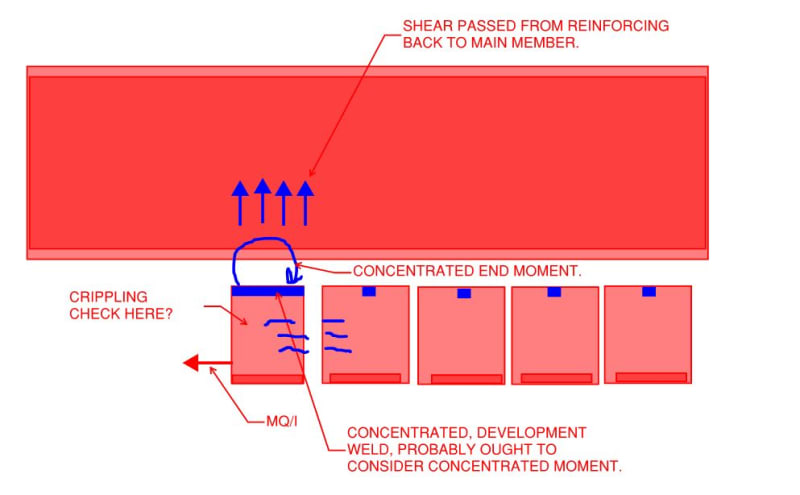
Some observations related to the revelation (to me) that partial reinforcement has end moments.

1) This statement is no longer true in the sense that I'd intended it. Where the reinforcement would be set out asymmetrically, or the load asymmetrical, the reinforcement end moments may be unequal and thus produce a shear in the reinforcement which complicates / neuters my efforts at simplification.

KootK said:
1) No matter how you set out the reinforcement, the horizontal shear forces induced by the welds will create a force set that generates no vertical shear in the reinforcement at all.

2) Recently, here on eng-tips, I've seen a number of folks advocate the use of W-shapes as reinforcement rather than WT-shapes. The logic being that top side flange welding is easier than underside T-stem welding. But the issues raised here complicate that somewhat.

3) Even with traditional, WT-shape reinforcing, I still see a problem. It seems reasonable to me that the MQ/I concentrated weld should also resist the reinforcing end moments which is something that I've never seen discussed in print. To varying extent, this issue would afflict all forms of reinforcement that possess significant, independent Ix's. So flange plates, flange channels, rods, and small angles would be relatively insensitive to this phenomenon. But stacked wide flanges, WT-shapes, large angles, and channels welded to girder webs should consider it.

c02_fxndl3.jpg
 
dik said:
@Koot... what is the parabolic function, if I may ask?

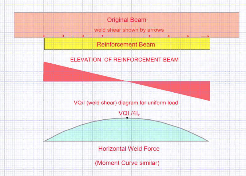
The anchorage force is the sum of horizontal shear from the end of the reinforcement beam to the section under consideration. It is zero at each end and maximum at the point of zero shear. It can be shown to be parabolic if the load is uniform (see below).

If the weld shear were the only effect at play, the reinforcement beam would arch upward, but the uniform load acting downward on the original beam prevents upward arching. In effect, the reinf. beam uses part of the applied load to counteract upward arching.

image_xtmiie.png


BA
 
KootK said:
I haven't bothered to work out the details dik. I just know that it takes a parabolic form from mechanics of materials. My first step in checking BA's stuff was to reverse the roles of the main member and reinforcement to see if the total equaled 100% of the total shear. It was off by a significant margin. This is why. BA's approximation is more applicable to some cases than others. Which is fine, of course, as that's usually the way of things with approximation.

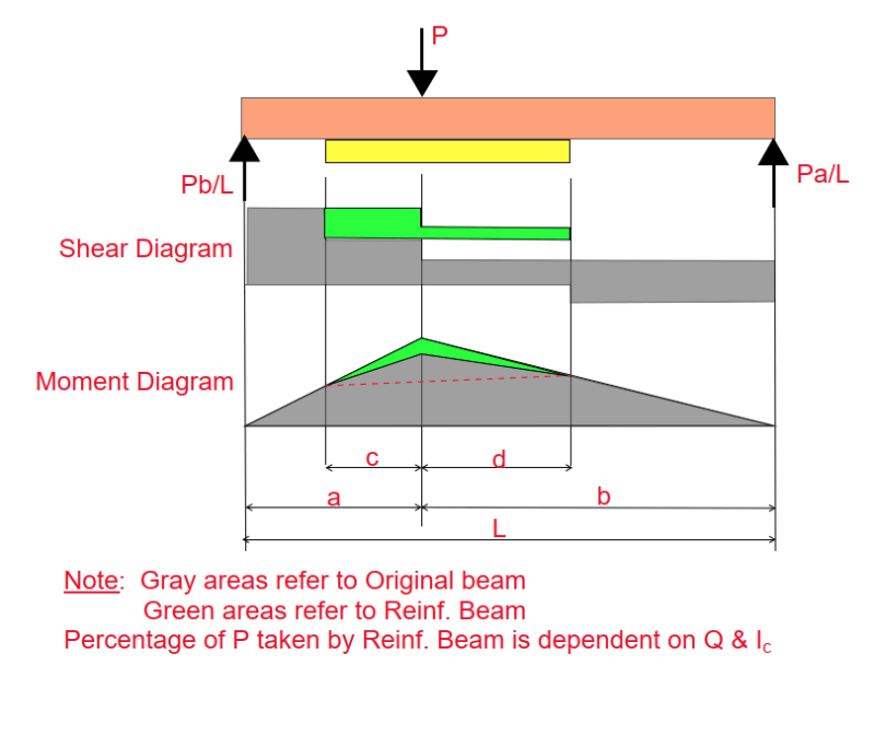
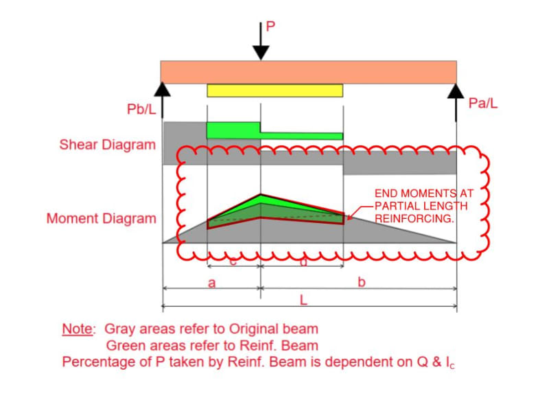
It really isn't an approximation. It can't be off by a significant margin. Consider the performance of a built up beam with a single point load. The percentage of P taken by the reinforcement beam is dependent on Q, h and Ic. The shear and moment diagrams are illustrated below.

If it works for a single load, then, by the principle of superposition, it works for any combination of point loads.

image_r76euk.png


BA
 
Thanks BART... clear as mud, with the required reactions equal to the shear values shown by the green SFD portion. UDL would be similar approach, but would have slightly different diagrams. The BMD doesn't even come into play... thanks gentlemen... You can use the added moment to determine the length of the added member (which you should have done anyway) and use that moment to calculate the added q and use that q to determine reactions. I've always extended the add on section for a depth beyond the point of cutoff, but there is no need for that.

Rather than think climate change and the corona virus as science, think of it as the wrath of God. Feel any better?

-Dik
 
BAret said:
It really isn't an approximation.

With regard to the parabolic approximation that I mentioned, your last couple of posts have been addressing something entirely different from what I'd intended. My intention is shown below.

C01_zitkl9.jpg


C01_mfe62a.jpg
 
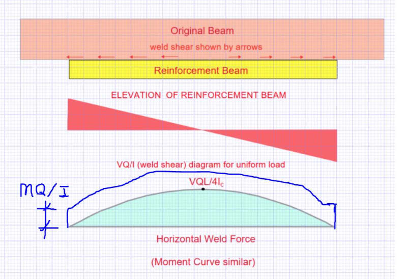
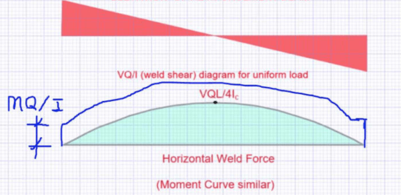
@BAret: I believe that your recent diagrams need the modifications shown below. The first is just MQ/I; the second represents the "disturbed region" business that steveh49 and I were discussing earlier in the thread.

C01_tzytwr.jpg


c02_tc45nc.jpg
 
First, there was a typo in one of my earlier posts (2 Apr 21 20:00)

Tension from weld to reinf. beam = T = V*Q/Ic *L/2 *Edit: i2 should read 1/2 = V.Q.L/4Ic

In the above, T is the total tension applied to the reinf. beam by the weld each side of midspan.
It is the area under the shear diagram of half the reinf. beam. Its units are force.
image_wlhhcz.png

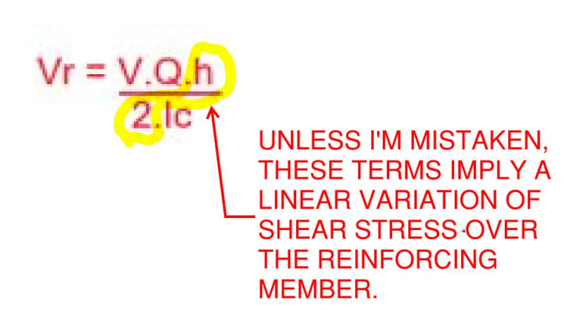
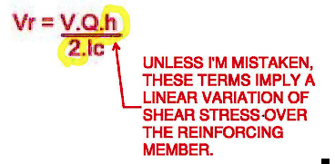
In the above sketch, Vr is the calculated shear at the end of the reinf. beam. Its units are force.

KootK is not mistaken; shear stress varies linearly over the reinf. beam. It has a value of Vr at each end and tapers linearly to 0 at midspan.

image_th2us8.png

In the above sketch, the red shading indicates the linear variation of shear stress. The value at each end is Vr in units of force.

The suggestion of a value of MQ/I at each end is incorrect. The tension at any point is the area under the shear diagram (summation of shear force) between the end of the beam and the point under consideration. It could also be called the anchorage force and is parabolic in shape when the applied load is uniform.

As noted, the moment curve is similar, varying only by a factor of h/2.

I hope this clears up any misunderstanding.


BA
 
Yup... that's what I understood from posting of 4:45... CAM, again...

Rather than think climate change and the corona virus as science, think of it as the wrath of God. Feel any better?

-Dik
 
BAret said:
In the above sketch, the red shading indicates the linear variation of shear stress. The value at each end is Vr in units of force.

Again, I am not concerned with the variation of stress along the length of the beam. Rather, I am concerned with the variation of stress over the height of the reinforcing member which is parabolic and not linear under all conditions of load. In your calculations, are you not calculating the shear in the reinforcement at its ends as the area under the relevant portion of the diagram below? If so, that would be integration over a parabolic function rather than a linear one, would it not? Or are you attempting to calculate Vr as the sum of the area under the VQ/I diagram over the shear span (incorrect in my opinion)?

BAret said:
The suggestion of a value of MQ/I at each end is incorrect.

I strongly disagree for the case of partial reinforcement. What is it you think MQ/I does if not this?

BAret said:
The tension at any point is the area under the shear diagram (summation of shear force) between the end of the beam and the point under consideration.

That is true but, in the case of partial reinforcement, MQ/I is precisely the "missing" portion of VQ/I that would have been present if the reinforcing extended the full length of the beam. These two statements are therefore equivalent:

1) The total anchorage force is the summation of VQ/I over the shear span of the ORIGINAL member imagining that the partial reinforcing had run the full length and;

2) The total anchorage force is the summation of MQ/I + VQ/I taken over the shear span of the REINFORCING member.

C01_ynynar.jpg
 
dik said:
@Koot... what is the parabolic function, if I may ask?

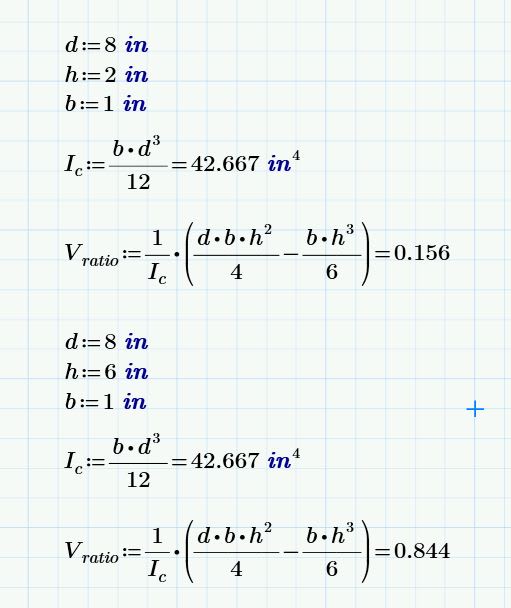
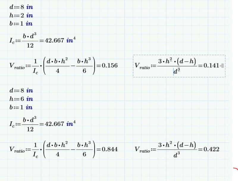
Because I'm a glutton for punishment, and because I want to do my share of the heavy lifting, I went ahead and attempted the integration. My result is shown below. As I predicted, it's slightly more than BAret's [0.14 * V]. It's also a cubic function which makes sense given that it's the integration of a parabolic function.

Below, I've also run the case where the roles of the main member and the reinforcing are reversed. The value that it yields is [1.00 - 0.156 = 0.844] which, again, jives with one's intuition.

C01_vmjao7.jpg
 
KootK, I did not use that triangle in my analysis. V[sub]x[/sub]Q/Ic is the horizontal shear per unit length in the pair of welds between upper and lower beams. (V[sub]x[/sub]Q/Ic)*L/2*1/2 is the total anchorage force at midspan, assuming uniform load. Anchorage force at the end of the lower beam is zero. It increases at a decreasing rate toward midspan.

Integrating the triangle shaded red (or the area under the curve) is not relevant to the question at hand.

image_am1a4g.png


BA
 
KootK said:
BA[/color]]Again, I am not concerned with the variation of stress along the length of the beam. You should be. Rather, I am concerned with the variation of stress over the height of the reinforcing member which is parabolic and not linear under all conditions of load. You should not be concerned about this as it is not relevant.

In your calculations, are you not calculating the shear in the reinforcement at its ends as the area under the relevant portion of the diagram below? NO!!!

If so, that would be integration over a parabolic function rather than a linear one, would it not? It would be if that was what I was doing. Or are you attempting to calculate Vr as the sum of the area under the VQ/I diagram over the shear span incorrect in my opinion)? Yes, indeed, that is what I am doing (correct in my opinion).

BA
 
BAret said:
KootK, I did not use that triangle in my analysis. VxQ/Ic is the horizontal shear per unit length in the pair of welds between upper and lower beams. (VxQ/Ic)*L/2*1/2 is the total anchorage force at midspan, assuming uniform load.

If that is the case, then I'm afraid that I don't understand your methodology. Can you post some kind of sketch to show how the horizontal shear can be used in this way to arrive at the correct value of the vertical shear in the reinforcing?

BAret said:
Integrating the triangle shaded red (or the area under the curve) is not relevant to the question at hand.

I disagree strongly with that assertion. As far as determining the shear in the reinforcing member goes, I consider the integration of the VQ/I function over the height of the reinforcing to be pretty much the gold standard as it's classic textbook stuff rather than our own handiwork.

Below, I've compared my latest equation on the left with your equation on the right, as I understand it. I've also reversed the variables so as to determine the shear carried by each member of the assembly. My values add up to 1.00 as one would expect given that all of the global shear must me carried somewhere. Your values add up to 0.563 which would seem to leave 43.7% of the global shear unaccounted for. Are you able to reconcile that somehow?

C01_ajqmcp.jpg
 
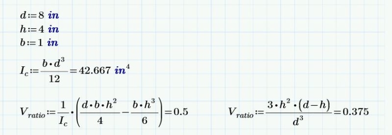
Here's another version assuming the reinforcement to be the same depth as the main member. Clearly, the shear carried in the reinforcing is 50% in this case, right? Symmetry?

C01_yz2ghl.jpg
 
Edit: I botched the description of the horizontal shear flow, it's not the area of the parabolic curve but rather the value of tau at the interface which is what you are concerned with for the attachment determination. Not sure why you are trying to get the area of the tau curve as that is not what the shear flow is, the shear flow is tau at the specific elevation of the fasteners x the length between fasteners. The anchorage force is the sum of the dx shear flow again at the fastener interface where integral V*Q/I*b dx = Q/I*b integral V dx where integral V dx is equal to moment, M
(removed the image will redo the sketch and add it back)

Now with a reinforcing section of significant depth you have shear lag to contend with which should probably be taken into account when looking at the anchorage length.

edit2: Image showing the shear lag
Capture_iibnh3.jpg


My Personal Open Source Structural Applications:

Open Source Structural GitHub Group:
 
Status
Not open for further replies.

Part and Inventory Search

Sponsor