Continue to Site

Eng-Tips is the largest engineering community on the Internet

Intelligent Work Forums for Engineering Professionals

  • Congratulations KootK on being selected by the Eng-Tips community for having the most helpful posts in the forums last week. Way to Go!

Partial Steel Beam Reinforcement Anchor Force 7

Status
Not open for further replies.

Baffled Engineer

Structural
Jul 27, 2018
56
Hello,

I'm working on a steel beam reinforcement consisting of a new W-shaped beam welded below an existing W-shaped girder, which looks like this:
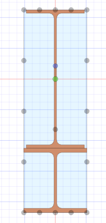
Girder_Reinforcement_xihayd.png


I'm trying to determine the anchorage force and extension required for partial reinforcement. According to my reference below from the Canadian Steel Handbook, the formula provided consist of the area of the reinforcement times the distance from the centroid of the reinforcement to the centroid of the entire combined section, which is the same variable (Q) used in shear flow calculations. My question is, would this formula still apply to my W-shaped reinforcement? Or is it limited to cover plates?

I'm concerned that there's an implicit assumption that the plate has uniform stress if assumed to be thin, and with the W-shaped reinforcement, there is a considerable stress distribution across the depth of the section. Any thoughts on this? Thanks.
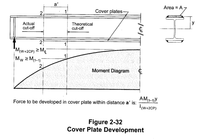
Reinforcement_Development_ttgl9i.png
 
Replies continue below

Recommended for you

Was that the Jabberwocky?

Rather than think climate change and the corona virus as science, think of it as the wrath of God. Feel any better?

-Dik
 
BAretired, referring to your posts 7/4/21 16:04 & 23:28:

If I've understood correctly, the moment diagram you've drawn is due to the distributed horizontal shear force (shear flow) applied to the top edge of the reinforcement section. This is eccentric to the reinforcement centroid so could be considered a concentric distributed axial force and distributed torque. The moment diagram is the integration of the torque.

In that case, there is no shear force associated with the bending moment and no vertical reaction at the ends. It is the distributed case of a beam with equal/opposite end moments.
 
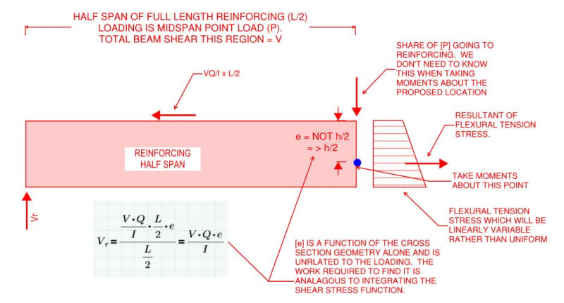
@BAret: the center of tension in the reinforcement is not located at h/2 but, rather, closer to the outer edge of the member. That, owing to the fact that there's a flexural tension stress gradient across the height of the reinforcing. The stress diagram is a trapezoid, not a rectangle. I believe that this would increase your predicted reinforcing end shear, perhaps bringing it in line with my formulation (I haven't verified the algebra yet).

Any chance that strikes a chord with you as a possible point of reconciliation?
 

Since the NA of the composite section may be in the section above, would that not cause the centre of tension to move up towards the upper member, and not towards the outer edge? or, am I misunderstanding something here?

Rather than think climate change and the corona virus as science, think of it as the wrath of God. Feel any better?

-Dik
 
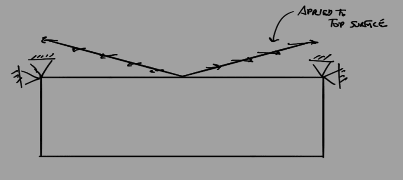
FEM backup for what I believe BA is referring to, cross section restrained at each end at the top outside corners with a varying axial load, VQ/I, applied at the top surface. Yields horizontal reactions only:
Screenshot_from_2021-04-08_08-47-10_qsumsn.png

Screenshot_from_2021-04-08_09-09-02_kdhjob.png

Screenshot_from_2021-04-08_09-09-11_y1502k.png


The same but this time with fixed restraint on the corner nodes:
Screenshot_from_2021-04-08_09-09-33_vcoc2l.png

Screenshot_from_2021-04-08_09-09-39_l5ctjc.png


Edit:had the load direction reversed

My Personal Open Source Structural Applications:

Open Source Structural GitHub Group:
 
Celt83, could you share some details of this analysis:

Screenshot_from_2021-04-07_15-55-49_fldxzy_qgi407.png


- This image shows vertical stress?
- Span and reinf length?
- Loading?
- The two cross sections?
- Is there a stiffener at the reinf termination?
- Pin-pin or pin-roller?
- What are the forces at the red hotspot and the blue balloon near the reinf termination point? Looks like a tension hanger force compression and balloon (a couple aka concentrated moment).

Thanks.
 
And in this image, is the red hot spot actually a hot spot or just M*y/I bending stress based on the shallower section properties? What is the red stress magnitude and what is the blue stress at the top face directly above?

Screenshot_from_2021-04-07_15-55-57_zkxs9j_c41eb4.png
 
- This image shows vertical stress? Correct Vertical Shear Stress
- Span and reinf length? 10ft overall span with reinforcement from 3ft to 7ft (modeled as two shells but ultimately share mesh interface)
- Loading? 1kip/ft vertical load applied at the top of the main shell
- The two cross sections?b=6" h=12" main shell, b=6" h=6" reinf. shell
- Is there a stiffener at the reinf termination?nope
- Pin-pin or pin-roller?pin roller, supports located at mid depth of the main shell left side pin xyz right side pin yz roller x
- What are the forces at the red hotspot and the blue balloon near the reinf termination point? Looks like a tension hanger force compression and balloon (a couple aka concentrated moment).dumped the file after the screencaps, only takes a minute or two to put together so can pull this info sometime later.


And in this image, is the red hot spot actually a hot spot or just M*y/I bending stress based on the shallower section properties? What is the red stress magnitude and what is the blue stress at the top face directly above?actually not 100% on this will recheck along with the above

My Personal Open Source Structural Applications:

Open Source Structural GitHub Group:
 
Thanks. I thought the first image was vertical direct stress. Will have to think some more...

Any chance of a vertical direct stress plot? I am on a phone without a real computer for a while.
 
dik said:
Since the NA of the composite section may be in the section above, would that not cause the centre of tension to move up towards the upper member, and not towards the outer edge? or, am I misunderstanding something here?

Not as I'm envisioning it dik. What follows should clear that aspect up.

Here's my modified version of what I suspect BA's method is:

1) Choose to work with a single point load for two reasons:

a) Since the proportion of the vertical shear going to the reinforcement will be agnostic to the loading, pick a load that simplifies things knowing that the results will translate fully to other situations. Moreover, all loads can be envisioned as a collection of point loads if desired.

b) A single concentrated load is a fine choice to work with because it results in no transvers load on the reinforcement member along the shear spans. And that simplifies the free body diagram that will come next.

2) Use the free body diagram below which includes all of the loads present on A full length reinforcement half span to work out the reinforcement end shear and end reaction.

C01_vembr9.jpg
 

Thanks...

Rather than think climate change and the corona virus as science, think of it as the wrath of God. Feel any better?

-Dik
 
It seems to me that we can calculate flexural stresses directly from the moment on the composite section, which is readily found. The problem we are having is in deciding how much reaction the reinforcing beam takes.

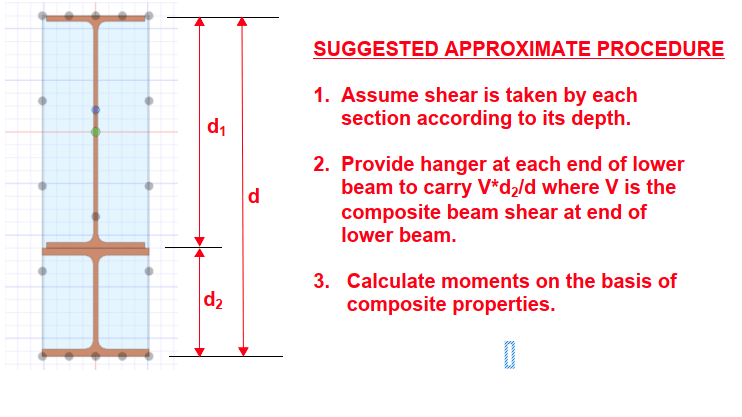
The following approximate procedure is not exact, but is thought to be conservative. Anything more exact is likely not worth the calculation effort.

image_vxn2yf.png


BA
 
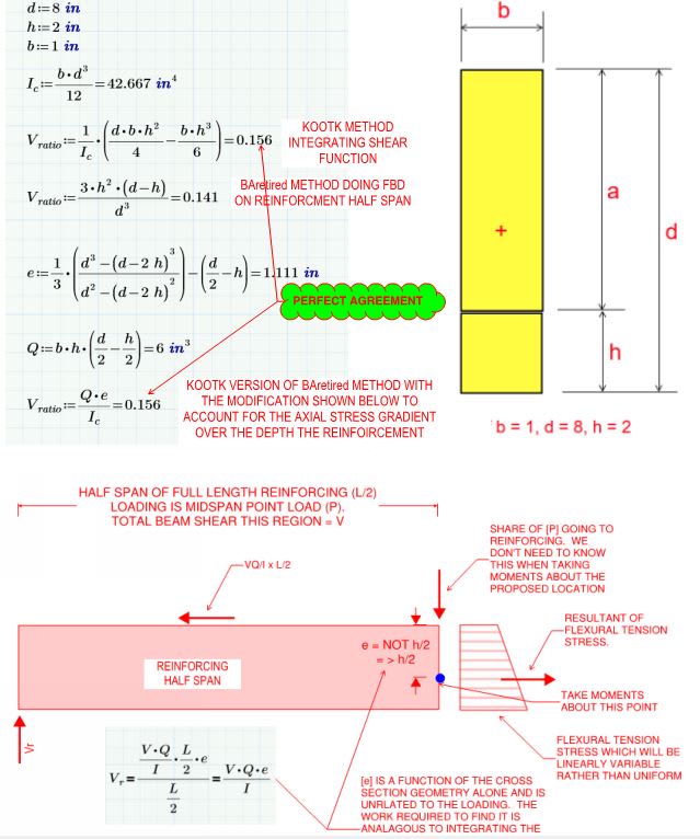
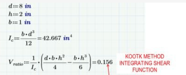
@BAretired: I'm pretty sure that I've got this sorted out now. I executed what I believe to be the corrected version of your method as I proposed in my last post. It now produces the exact same result as my original method of integrating the shear stress function over height of the reinforcement. Unless someone can poke a hole in what I've done, I consider this "case closed".

C01_ju6zxj.jpg
 
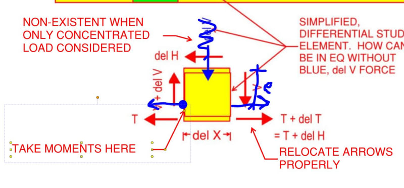
Interestingly, my differential element study from the top would produce the same result for a concentrated load when the location of the delT force is made accurate. I'd recognized that discrepancy at the time and it was actually what prevented me from attempting to estimate the vertical shear in the reinforcing then.

KootK Long Ago said:
For convenience, I've pretended that all of the flexural tension resides in the lower flange.

C01_wqtbrb.jpg
 
BAretired said:
Anything more exact is likely not worth the calculation effort.

So all along I've been thinking to myself "easy enough for a rectangle but what about wide flange reinforcing? Meh, we'll leave that for later".

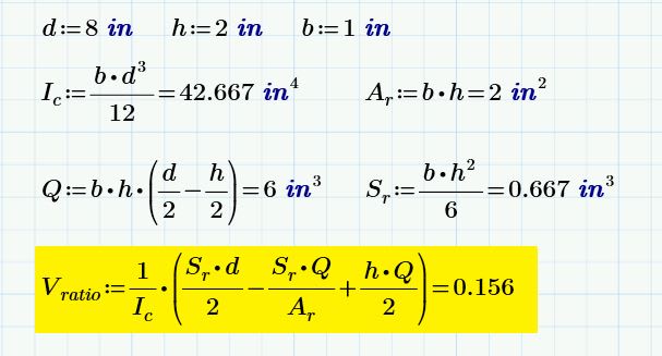
Later is now. I did the algebra and this works out fairly simply for any reinforcing cross section using only properties that a designer will have on hand after the basic reinforcing design is complete:

1) Ic = composite moment of inertia.
2) Q = the usual value.
3) Sr = the section modulus of the reinforcing alone.
4) Ar = the area of the reinforcing alone.

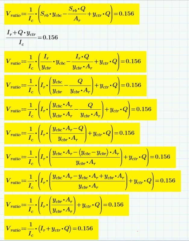
It reduces to the equation yellow below which would be multiplied by the overall beam shear to get the shear in the reinforcing and hanger load.

The equation should be valid for any shape: rectangle, wide flange, tee, flat plate...

EDIT: I think this will only work for vertically symmetric reinforcement as shown. So not tee's just yet...

C01_gkce3m.jpg
 
You get a little purple star just for the shear effort!! No pun intended.

image_moskxb.png


The suggested approximate formula yields V[sub]ratio[/sub] of 2/8 = 0.25 (very conservative)

If: d = 8", h = 4", b = 1"
then, by the KootK formula, V[sub]ratio[/sub] = 0.5

The suggested approximate formula yields V[sub]ratio[/sub] of 4/8 = 0.50 (perfect)


BA
 
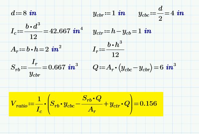
This should be the truly general version of the formula that would apply to all shapes, symmetrical or not, including tees. For sport, I again ran it against the rectangle example. It would be more meaningful to run it against a wide flange reinforced with a tee. However, I may never get around to doing the integration on that for verification.

1) I_c = composite moment of inertia.
2) Q = first moment of area about the weld line.
3) S_rb = the section modulus of the reinforcing alone referenced to the bottom of the section.
4) A_r = the area of the reinforcing alone.
5) y_cbc = distance from centroid of composite section to the bottom of the reinforcing.
5) y_cbr = distance from centroid of reinforcing alone to bottom of reinforcing.
6) y_ctr = distance from centroid of reinforcing alone to top of reinforcing.

C01_cevuph.jpg
 
Vreinf / Vtotal = (Ir + Qr * Cr) / Ic

Ir = I of reinforcement about own centroid
Qr = Q of reinforcement when considered as part of composite section (the usual Q value)
Cr = distance from centroid of reinforcement to interface with the main section
Ic = I of the composite section

Explanation:
The trapezoidal longitudinal stress on the reinforcement is separated into an axial (force) component acting at the centroid of the reinforcement, and a moment component.

The axial force component = Qr/Ic * Mtotal.
The moment component = Ir/Ic * Mtotal.

Draw a free body diagram of the reinforcement similar to KootK, including the shear flow (= the change in axial force over the length of the FBD) and the equal/opposite reinforcement shear force at each end.

Sum moments to zero and rearrange to find Vr/Vtotal.

Edit: this is the same as KootK's equation (but I think neater and provides more insight). KootK's Srb terms are a convoluted way of writing Ir. This would be because KootK approached from a different direction (stress vs force/moment).
 
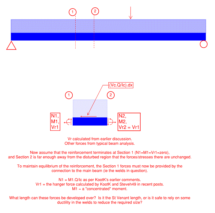
And now that's settled, I want to move back to the question of reinforcement that terminates within the span rather than running full length. There's only one question left in my mind, which was raised earlier. Hopefully the image below is self-explanatory, and the North American crew solves it while I sleep.


ReinfTermination_pmg1fm.gif


Edit: N1 = (M1,total).Q/Ic, not calculated from just the reinf moment.
 
steveh49 said:
Edit: this is the same as KootK's equation (but I think neater and provides more insight).

It's beautiful steveh49. I've compared it against my stuff both numerically and algebraically and it checks out 100%. The algebra took a little doing. I feel like I'm in the 11th grade all over again this week. I'll noodle on your latest question over the weekend. For now, what does the term "St. Venant length" mean to you? I'm familiar with St. Venant's principal but not St.Venant's length. Is it a particular value or multiple of the member depth? Or just a concept, that of being far enough away from disturbances that the net effect is equivalent to a statically equivalent setup without the disturbances.

C01_elt5mu.jpg
 
Status
Not open for further replies.

Part and Inventory Search

Sponsor