Continue to Site

Eng-Tips is the largest engineering community on the Internet

Intelligent Work Forums for Engineering Professionals

  • Congratulations KootK on being selected by the Eng-Tips community for having the most helpful posts in the forums last week. Way to Go!

Partial Steel Beam Reinforcement Anchor Force 7

Status
Not open for further replies.

Baffled Engineer

Structural
Jul 27, 2018
56
Hello,

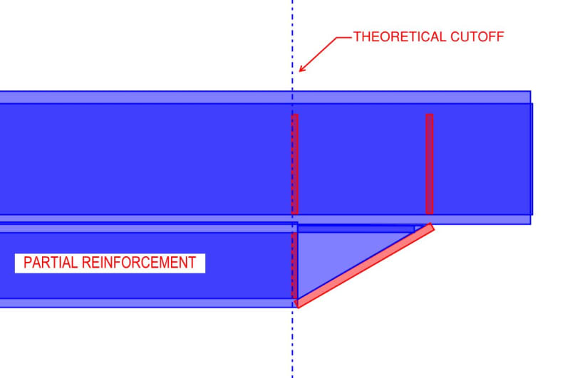
I'm working on a steel beam reinforcement consisting of a new W-shaped beam welded below an existing W-shaped girder, which looks like this:
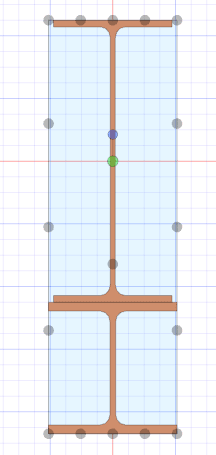
Girder_Reinforcement_xihayd.png


I'm trying to determine the anchorage force and extension required for partial reinforcement. According to my reference below from the Canadian Steel Handbook, the formula provided consist of the area of the reinforcement times the distance from the centroid of the reinforcement to the centroid of the entire combined section, which is the same variable (Q) used in shear flow calculations. My question is, would this formula still apply to my W-shaped reinforcement? Or is it limited to cover plates?

I'm concerned that there's an implicit assumption that the plate has uniform stress if assumed to be thin, and with the W-shaped reinforcement, there is a considerable stress distribution across the depth of the section. Any thoughts on this? Thanks.
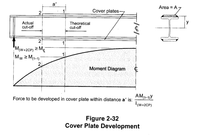
Reinforcement_Development_ttgl9i.png
 
Replies continue below

Recommended for you

I agree with the end stiffeners and was going to point out that they should be at the end of the reinforcement rather than where first drawn but you got in with the current detail first. I also thought my local code had a requirement not to rely on mixed bearing/weld connections but that doesn't seem to be the case. I would then only have the end stiffener; I think that a little flange flexibility will avoid excessive compatibility stresses. It is still the case that any varying reinforcement shear is caused by varying overall shear and not varying moment; and that the disturbed zone is a different beast than the interior which I thought wasn't coming out in the discussion.
 
The stiffeners at the ends makes sense to me as they provide stability and load transfer of the vertical shear component in the reinforcing beam back into the existing girder. I would have to design for those stiffeners in addition to the anchorage forces from the horizontal shear flow. Thanks guys I appreciate the help.[bigsmile]
 
steveh49 said:
It is still the case that any varying reinforcement shear is caused by varying overall shear and not varying moment;

I disagree. Shear and moment come as a compatible set that can't really be separated. Varying reinforcement shear absolutely will be accompanied by varying global shear AND varying moment. To say that one is the "cause" and the other is not is spurious in my opinion.

steveh49 said:
...and that the disturbed zone is a different beast than the interior which I thought wasn't coming out in the discussion.

I agree, the transition surely is a disturbed region. What do you propose for dealing with that? My thinking has been:

1) Do the stiffener as proposed so that, at worst, you might rupture some welds at the end of the reinforcement but not rip the thing clean off.

2) Design the MQ/I welds to also perform the "hanger" job at the end of the beam so reduce the odds of rupturing any welds. Luckily, this will naturally be a location of concentrated welding.

3) As you said, hope that flange flexibility helps to relive any stresses arising from compatibility. This would tend to be more true further from the stiffener I think.
 
I feel that an interesting follow up to this is the question of how much shear winds up in the reinforcement and needs to be dealt with at the stiffener? One robust way to do that is to simply integrate VQ/I over the depth of the reinforcement. That said, while I struggle to find a way to prove this rigorously in the general case, I believe that the following is true, at least for simply supported beams:

1) No matter how you set out the reinforcement, the horizontal shear forces induced by the welds will create a force set that generates no vertical shear in the reinforcement at all.

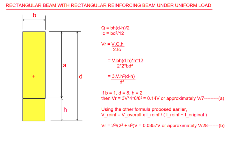
2) Because of #1, the shear carried in the reinforcement will be that which you would expect if the original beam and reinforcement beam were acting non-compositely: V_reinf = V_overall x I_reinf / ( I_reinf + I_original ).

I find these results surprising and am curious to know if others see this differently.
 
KootK said:
1) No matter how you set out the reinforcement, the horizontal shear forces induced by the welds will create a force set that generates no vertical shear in the reinforcement at all.

2) Because of #1, the shear carried in the reinforcement will be that which you would expect if the original beam and reinforcement beam were acting non-compositely: V_reinf = V_overall x I_reinf / ( I_reinf + I_original ).

I find these results surprising and am curious to know if others see this differently.

I agree with #1, but not with #2. Gravity load is required to counter the upward curvature caused by the shear induced by the weld. Additional load is required to bring the reinforcing beam down to the compatible deflection.

I have not really thought it through thoroughly, but I suspect the shear to be taken by the stiffeners would be approximately equal to V[sub]1[/sub] * h[sub]r[/sub].t[sub]r[/sub]/(h.t + h[sub]r[/sub].t[sub]r[/sub]) where V[sub]1[/sub] is the shear at the end of the reinforcing beam and the product of h*t represents web area of the upper beam and the subscript 'r' refers to the reinforcing beam.

EDIT: A more accurate method would be to calculate the deflection of the composite beam, then the reinforcing beam, keeping in mind the correction for curvature due to weld.

BA
 
BAretired said:
Gravity load is required to counter the upward curvature caused by the shear induced by the weld. Additional load is required to bring the reinforcing beam down to the compatible deflection.

Right, but the shear proposed below would be be that associated with exactly that gravity load. Part of it would nullify the upwards curvature due to the weld shear and the remainder would push the reinforcing down to the appropriate elevation in the deflected, composite beam. If all of the proposed load went towards downwards curvature, starting from level, then it would push the reinforcing down too far and composite behavior would not be captured.

V_reinf = V_overall x I_reinf / ( I_reinf + I_original )
 
In the proposed formula:
V_reinf = V_overall x I_reinf / ( I_reinf + I_original )

I_composite is not mentioned, but it determines the actual deflection of the beam.

BA
 
BAretired said:
I_composite is not mentioned, but it determines the actual deflection of the beam.

I_comp does determine the deflection of the beam but not the total shear in each of the two parts. That's why I said it was surprising.
 
KootK said:
Shear and moment come as a compatible set that can't really be separated. Varying reinforcement shear absolutely will be accompanied by varying global shear AND varying moment. To say that one is the "cause" and the other is not is spurious in my opinion.

That's the case, but I was responding to your statement quoted below, where might follow from [a] but not necessarily. 'Cause' and 'effect' are ok in this context IMO because the external load causes the shear to change, at least in Australian vocabulary where we call shear force/bending moment/etc 'design action effects', ie the effects caused by design actions (loads).

"a) One requires the new, low flange force to vary along the length of the beam.
b) [a] dictates that the reinforcing member horizontal shear increases along the length of the beam."


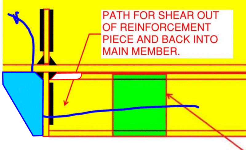
On to the more interesting discussion above, I admit I've lost track of whether it's in relation to the B-region or the D-region in places. I'm also going to hedge by saying I too haven't come to a satisfactory conclusion in my own mind but think the stiffener force will be related to several stiffnesses that would be complex to assess. At the termination of the reinforcement, the overall bending moment is essentially the same on the unreinforced and reinforced side, but the Bernoulli curvature M/EI should be quite different. Assuming there's enough flexibility or ductility to avoid failure, the stiffness of the connection will determine how quickly the moment is split between the main beam and the reinforcement (over what length unequal curvature occurs between main beam and reinforcement), and therefore the magnitude of the forces involved. Coping the top flange of the reinforcement near the stiffener is something I'm toying with to introduce flexibility and move the force couple further apart.
 
I'm in the happy territory of knowing this is over-thinking but also under-thinking at the same time.


c01_tyvwef_w6qofu.gif


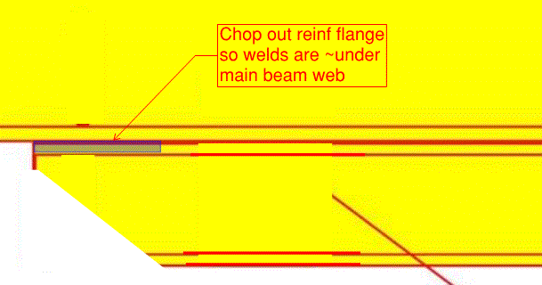
Edit: Or maybe chop out most of the reinf top flange width at the end, do away with the stiffeners, and just have web-to-web welds for a length aka the reinf section is an inverted tee at the end.
 
steve49h said:
I'm in the happy territory of knowing this is over-thinking but also under-thinking at the same time.

That would be a pretty great detail from an engineer's perspective. I'd also thought of partial coping as an attractive solution. Of course, as is probably the case with most engineers, I'd back off in practice to just the stiffener for fear of being considered -- and possibly truly being -- ridiculous.
 
fear of being considered -- and possibly truly being -- ridiculous

Right up there with fear of major collapse as a motive for engineer behaviour. I'm not being sarcastic, even if it sounds like it,

Which leads me to this detail. Less welding overall (replaced by gas cutting), no additional overhead welding, doesn't look ridiculous. The reason for going down this track is I'm still not sure whether the concentrated force that transverse stiffeners enable doesn't also have a downside. This structure matches the increase in section properties to the St Venant principle so there isn't any tendency for weld forces to deviate from weld capacity. Maybe St Venant means we don't need to cut out the lower left corner of the reinforcement.

c01_vrwcm8_tho68k.gif
 
Along similar lines, there must be a similar mechanism at play even in non-reinforced members under certain conditions of support detailing. After all, a non-built up member isn't so different from a built up member save the rather excellent connection at the interface.

c01_ffujvh.jpg
 
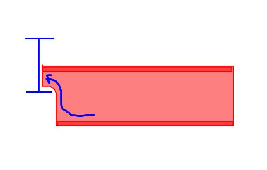
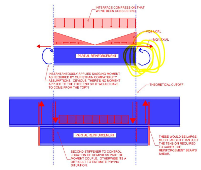
I'm beginning to think that we've been missing something important here. For the general case of partial reinforcement, I feel that a free body diagram of the reinforcing piece ought to include end moments as shown in my first sketch below. My second sketch shows a possible detailing arrangement to suit such a model.

c01_ahhijx.jpg
 
And then, of course, the next logical step would be something like this which starts to look like what any bridge engineer or PEMB designer would surely suggest for a variable cross section member...

c01_yr6pas.jpg
 
Koot, that moment is what I've been trying to address. The stress in the reinforcement can be thought of as a moment and axial force superimposed. As per BA, the flange welds introduce the axial force in a way that opposes the required moment so increase the concentrated moment. I don't know whether the couple will be too close with consequent weld-popping forces unless we make it be further apart or the stress development more gradual. And trying to do it without the second stiffener as a challenge.
 
Ahhh... Now I see the genius of your first detail. The back end stiffener does the moment job. Given that MQ/I and these end moments both dissipate towards the supports, I feel like it's generally a good idea to just run the reinforcement as near to the supports as spatial constraints will allow.
 
Tension from weld to reinf. beam = T = V*Q/Ic *L/2 *i2 = V.Q.L/4Ic

For uniform load on composite beam,
Mr = T.h/2 = V.Q.L.h/8Ic @ midspan varying to zero at supports (parabolic shape)

To balance Mr, we need Wr acting down on lower beam, which it gets from the upper beam bearing on it.

Wr*L/8 = V.Q.L.h/8Ic
Wr = V.Q.h/Ic
Vr = Wr/2 = V.Q.h/2Ic---------------------------------------------------(1)

Vr is reaction each end carried by stiffeners into upper beam.
Wr is total (virtual) load acting on reinf. beam
V is applied shear on composite beam @ each end of reinf. beam
Q is statical moment of reinf. beam.
h is height of reinf. beam.
Ic is moment of inertia of composite section.


BA
 
Following is a comparison between two proposed methods of calculating the stiffener reactions, assuming uniform load on the composite beam.

image_aglz2h.png


BA
 
Thanks BART... time for another SMath program... save me a lot of work... I owe you a beer...

Rather than think climate change and the corona virus as science, think of it as the wrath of God. Feel any better?

-Dik
 
Status
Not open for further replies.

Part and Inventory Search

Sponsor