Continue to Site

Eng-Tips is the largest engineering community on the Internet

Intelligent Work Forums for Engineering Professionals

  • Congratulations KootK on being selected by the Eng-Tips community for having the most helpful posts in the forums last week. Way to Go!

Partial Steel Beam Reinforcement Anchor Force 7

Status
Not open for further replies.

Baffled Engineer

Structural
Jul 27, 2018
56
Hello,

I'm working on a steel beam reinforcement consisting of a new W-shaped beam welded below an existing W-shaped girder, which looks like this:
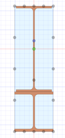
Girder_Reinforcement_xihayd.png


I'm trying to determine the anchorage force and extension required for partial reinforcement. According to my reference below from the Canadian Steel Handbook, the formula provided consist of the area of the reinforcement times the distance from the centroid of the reinforcement to the centroid of the entire combined section, which is the same variable (Q) used in shear flow calculations. My question is, would this formula still apply to my W-shaped reinforcement? Or is it limited to cover plates?

I'm concerned that there's an implicit assumption that the plate has uniform stress if assumed to be thin, and with the W-shaped reinforcement, there is a considerable stress distribution across the depth of the section. Any thoughts on this? Thanks.
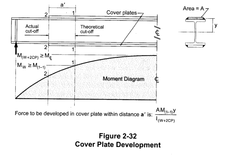
Reinforcement_Development_ttgl9i.png
 
Replies continue below

Recommended for you

Celt83 said:
Not sure why you are trying to get the area of the tau curve as that is not what the shear flow is, the shear flow is tau at the specific elevation of the fasteners x the length between fasteners.

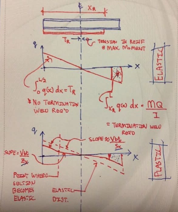
Because much of this thread is concerned with finding the vertical shear in the reinforcement and figuring out how that shear gets into, and more importantly out of, the reinforcing member when it is partial length. As discussed above, this requirement is in addition the the horizontal shear requirement (VQ/I).

BAretired and I actually discussed many of these same concepts with respect to the nature [MQ/I] in this previous, very informative thread. Folks following along may find that of interest. My perspective is/was summarized reasonably well in the posts surrounding the sketch below, reproduced from the previous thread.

C01_nbzkcc.jpg
 
I certainly agree with the shear lag business but consider that to be separate, and in addition to, the MQ/I business and the associated end moments in the reinforcing. The term "anchorage" is a bit problematic in this context as one might take that to mean any of the following:

1) MQ/I or;

2) VQ/I(partial) + MQ/I or;

3) VQ/I(full) or;

4) VQ/I(partial) + MQ/I + Shear Lag or;

5) VQ/I(full) + Shear Lag.

6) The old school practice of welding for [As x Fy] of the reinforcing at the ends, either in isolation or in combination with any of #1 through #4.
 
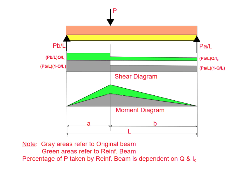
If the reinforcing beam runs full length of the original beam, under the action of a single point load, can we agree that the sketch below is accurate?

image_vuzhit.png


BA
 
BAret said:
If the reinforcing beam runs full length of the original beam, under the action of a single point load, can we agree that the sketch below is accurate?

I'm afraid not. I do very much like the idea of baby stepping through things in order to isolate the fundamental nature of our differences though.

C01_pcaayb.jpg
 
KootK said:
Because much of this thread is concerned with finding the vertical shear in the reinforcement and figuring out how that shear gets into, and more importantly out of, the reinforcing member when it is partial length.
Did not pick up on this, making more sense now.


My Personal Open Source Structural Applications:

Open Source Structural GitHub Group:
 
No worries, I'm glad to have your input on this as with all things first principles.
 
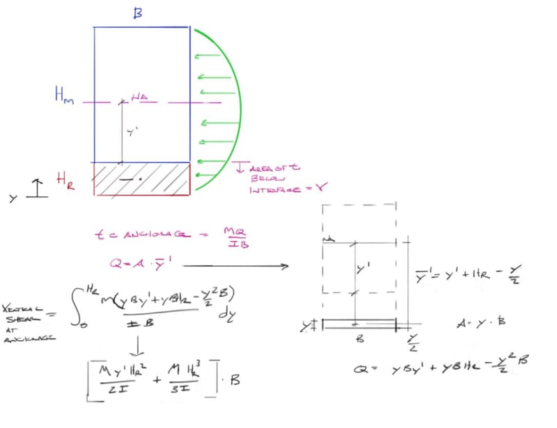
Ok I looked at tau based on the anchorage value since we are talking about the vertical shear in the end of the reinforcement, result looks pretty similar to yours.
assumes rectangular main and reinforcing section and uniform tau across the width.
Capture_a26eo1.jpg

edit: missed a B in the Q formula

My Personal Open Source Structural Applications:

Open Source Structural GitHub Group:
 
For a single concentrated load, the shear force and shear flow is constant and doesn't depend on the length of the beam or reinforcement. BAretired's method of integrating this over the reinforcement length to calculate the reinforcement hanging reaction would mean the reaction grows without limit as the length increases.
 
With respect to the question of what percentage of the total vertical shear is carried in the reinforcement, I see that as being completely determined by cross section geometry alone with no dependence whatsoever on the magnitude of the load nor it's distribution.
 
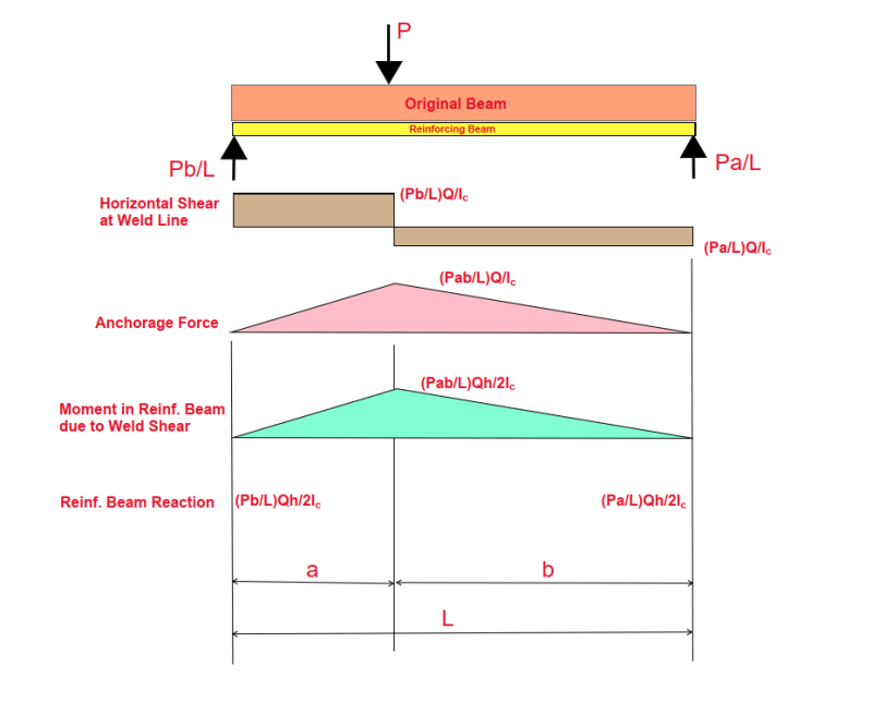
I have shown below the condition for full length reinf. beam with a single point load. I believe it is theoretically correct. Moment for the composite section is Pab/L, neglecting beam weight.

image_rhgvcm.png

BA
 
BAretired said:
I believe it is theoretically correct.

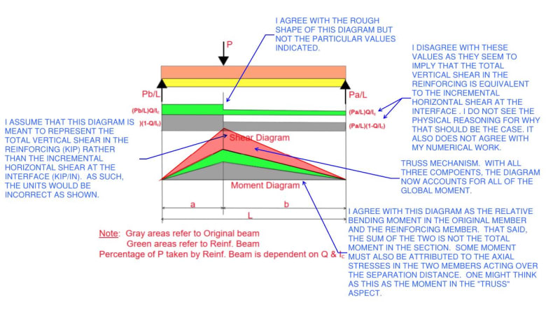
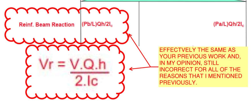
Are we headed towards an "agree to disagree" here? I previously pointed out what I believe to a number of numerical inconsistencies with your proposed reinforcing beam reaction estimates. Are you not interested in addressing any of that? It was my hope that, in exploring those things, we could reconcile our differences. I do agree with everything shown in your latest sketch other than the conclusion shown in the last line of it.

C01_w9tlm6.jpg
 
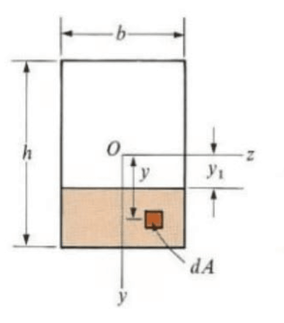
KootK, I am fully aware that you do not agree. I don't know how I can persuade you that your notion of integrating the curve is wrong. I am also aware that the vertical curve varies parabolically from top to bottom, but that does not enter the picture because the weld line shear already takes into account the parabolic variation with the term Q/Ic. For a rectangular cross section, such as you have shown, and I repeat below, Q/Ic has a maximum value of 3bh/2. This accounts for the fact that the maximum shear is 1.5 times the average shear.
image_ugykkr.png


If you agree with the second last line, i.e. the moment in the reinf. beam, then it is a mystery to me why you don't agree with the last line.


BA
 
I do not want to "agree to disagree". I would prefer to agree and I am perfectly willing to hear your arguments, but I'm afraid we are dragging the discussion out rather long for a situation so rare that I, for one, cannot remember ever having had to contend with in over fifty years of engineering practice. For others, it may not be so rare, so it is worthwhile getting it right.
 
BARetired said:
I am also aware that the vertical curve varies parabolically from top to bottom, but that does not enter the picture because the weld line shear already takes into account the parabolic variation with the term Q/Ic. For a rectangular cross section, such as you have shown, and I repeat below, Q/Ic has a maximum value of 3bh/2. This accounts for the fact that the maximum shear is 1.5 times the average shear.

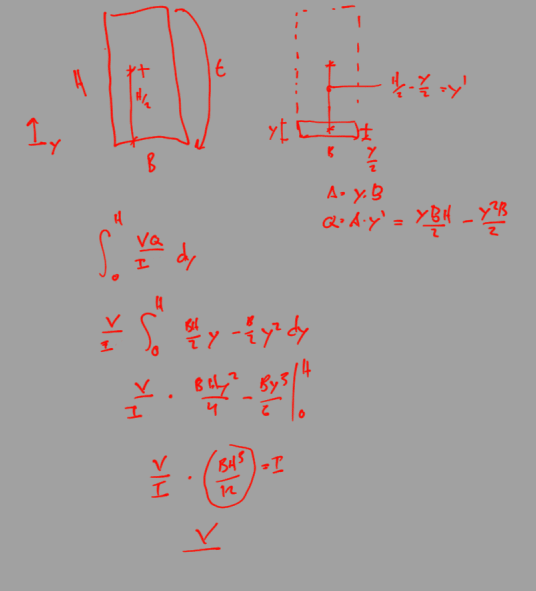
BA I believe this statement is incorrect, VQ/I is the horizontal shear stress at a specific slice in the overall section. You need to integrate once more to capture the full parabolic tau curve to yield total horizontal shear which also equals the total vertical shear.

Screenshot_from_2021-04-07_15-31-48_gps9mx.png


My Personal Open Source Structural Applications:

Open Source Structural GitHub Group:
 
Do you wish to continue or not BA? Call it and I shall respect your wishes. As you probably know, I rarely ever run out of steam on the deep dives. And I have several, targeted ideas for how we might move things forward if you're amenable to that. During the course of this discussion, I've already asked you several pointed questions that you've not made any explicit attempts to address. If you'd consent to attempting to answer my questions, I suspect that there's a fine chance that we could reach a consensus and that one or both of us could learn something valuable.

BAretired said:
If you agree with the second last line, i.e. the moment in the reinf. beam, then it is a mystery to me why you don't agree with the last line.

I was thinking the exact opposite. As far as I know, you've not explained the physical reasoning to support the logical step represented by going from your second to last line to the last line. Maybe you did explain that somewhere above and I just missed it somehow, I don't know. Would you humor me and, perhaps for the second time:

1) Explain the physical reasoning behind that step in words to the best of your ability.

2) Post a free body diagram that has the value shown clouded below shown on it someplace, in equilibrium with the rest of the forces in play? I've attempted this for you below but am sure that I've misunderstood as:

a) the free body diagram neglects some of the forces that are in play and;

b) the model would produce spurious numerical results as I mentioned previously. In the case with the stacked rectangles, it would predict a value other than 50% of the vertical shear in each piece with the joint located at mid-height (4"). Clearly that's not right.

c) it's not in vertical equilibrium without the transverse load applied to the top that we've long been discussing.

C01_ncq850.jpg
 
celt83 said:
KootK correct me if I'm wrong but I believe what your after is quantifying the force generating these stress concentrations...

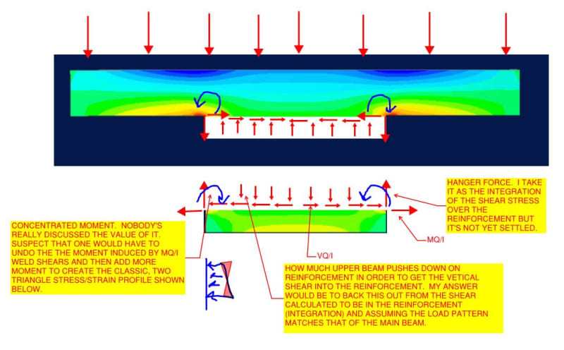
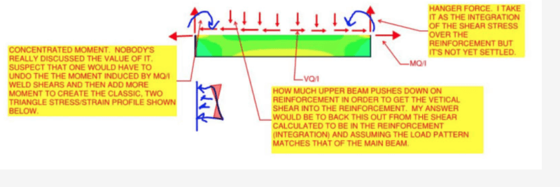
That's right. Your FEM output helps to illustrate this stuff nicely and I'm grateful for that. The items highlighted in yellow below indicate the values that I'm interested in determining, sketched on my understanding of what a complete FBD would be. It's been an exciting thread for me personally as I previously held a misconception about the distribution of vertical shear and didn't even realize that the end moments were a thing.

C01_okbnyd.jpg
 
@celt83: Tell me that doesn't make for a kick-ass diagram with my ideas superimposed on your FEM stresses?
 
Sorry I didn't respond earlier. One of the nurses at the health clinic called and advised that I could move my 'jab' from 7:30 tonight to right away, so I took the opportunity to do it. I have now had both jabs.

Anyway, VQ/Ib (#/in[sup]2[/sup] or N/mm[sup]2[/sup]) is the horizontal shear stress through any section of the beam. In particular, it is the horizontal shear stress at every section other than the weld line. On the weld line, the horizontal shear per unit of length (#/" or N/mm) is VQ/I.

VQ/I causes a net compression and tension in the original and reinforcement beam respectively. It is applied at the edge of each beam and, in both cases, causes upward arching, assuming no other forces acting.

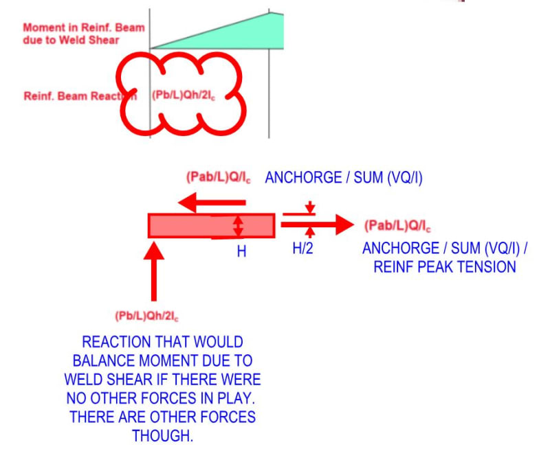
The moment from the weld force varies linearly from zero at the ends to a maximum at the load point. The reinf. beam reactions are consistent with the moment diagram, which you apparently agree with. I have shown the anchorage force and the resulting moment in my diagram above, also the reaction consistent with that moment. R[sub]left[/sub] = M[sub]max[/sub]/a; R[sub]right[/sub] = M[sub]max[/sub]/b. I consider it elementary statics and wonder what all the fuss is about.

KootK said:
As far as I know, you've not explained the physical reasoning to support the logical step represented by going from your second to last line to the last line.

I think I just did, but can expand on it if needed.

BA
 
image_ntvmv0.png


1) The value of the concentrated moment is zero. It does not exist.
2) The upper beam is lifting under the weld shear. It does contribute dead weight to the reinf. beam, but all the reinf. beam needs to balance the weld shear moment is the point load.
3) The hanger force is what I am calling the reinforcement beam reaction.
4) The arrows on the sketch representing horizontal weld force gives the impression that it is acting at the ends of the beam, but it is zero at both ends and maximum at the point load P.

BA
 
Status
Not open for further replies.

Part and Inventory Search

Sponsor