Continue to Site

Eng-Tips is the largest engineering community on the Internet

Intelligent Work Forums for Engineering Professionals

  • Congratulations KootK on being selected by the Eng-Tips community for having the most helpful posts in the forums last week. Way to Go!

PCC-2 Fillet Patches Clarifications 1

Status
Not open for further replies.

NovaStark

Mechanical
Feb 11, 2013
244
Hello All,

I am currently looking into the design of a fillet welded patch as per PCC-2 Article 212 due to external corrosion (local thin area) on a pressure vessel (designed to 2.2 MPa @ 180 degC with SA-516 Gr.60 material equivalent). As the vessel is designed to PD 5500, the minimum thickness is 13.7 mm with a nominal of 15 mm.

I would like to get some advice on the interpretation on some of the items in PCC-2.

From Paragraph 212.3-4(c), the load eccentricity check requires a minimum thickness of 44 mm. However, it appears this approach does not take into account the remaining strength of the initial shell. Is there any actual references on how to take this into account ?

Looking at Article 207 for patches with plug welds, there are formulas to determine the allowable loads on the plug welds however, the article doesn't actually state how these plug welds take up the eccentric loads. As the perimeter welds will still be present, the bending due to the eccentric configuration would still take place. Is this correct?

 
Replies continue below

Recommended for you

Based on my understanding, no cred is given to the remaining strength of the underlying shell in Article 207/212. This makes sense to me as a Patch Plate may used to reinforce a damaged area where the damage mechanism is not halted. The underlying remaining strength may not be present in the future.

My assumption regarding Article 207, is that the plug welds primary purpose is to prevent bending at the perimeter weld.
NB! I've not used Article 207 myself so I have no other experience with the method.

Related to bending stress at the perimeter weld, have a look at this thread
 
I've done a few of these over the years, and general things to consider

1) It is assumed that the patch will see the full design pressure. The scenario of concern is that even if a tiny hole appears in the parent material, the fluid will fill the cavity and expose the patch to the full vessel internal pressure

2) The calcs assume that the fillet weld thickness matches the patch plate thickness

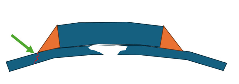
3) It's a bit grey then, but in general if you either 1) consider the throat thickness of the fillet weld or 2) consider the quality of the fillet weld (i.e. joint efficiency <1.0, you end up in the situation where the patch plate must with thickener than the parent materials Design thickness. At which point you can have a fillet weld that is larger than the parent material, which by judgment is not a good idea
patch_plate_ttcsma.jpg


4) Yes the plug welds are there to help with bending loads through the outer weld, but I believe also "help" transfer some of the other loads as well, I've never tried to analyze it before

5) I've usually ended up with a "fillet weld patches don't work" situation on most vessels, in particular vessels with and joint efficiency of 1.0, and minimal corrosion allowance. The end solution for me as been
a) do a full circumferential ring
b) Do an insert plate instead
b) go down the FEA route

Andrew O'Neill
Specialist Mechanical Engineer
Australia
 
Bjorn Nilsson said:
Based on my understanding, no cred is given to the remaining strength of the underlying shell in Article 207/212. This makes sense to me as a Patch Plate may used to reinforce a damaged area where the damage mechanism is not halted. The underlying remaining strength may not be present in the future.

My assumption regarding Article 207, is that the plug welds primary purpose is to prevent bending at the perimeter weld.
NB! I've not used Article 207 myself so I have no other experience with the method.

Related to bending stress at the perimeter weld, have a look at this thread

Yes I have read through that the thread referenced. I will take a closer look at article 207 but I don't recall it explaining in detail about how the plug welds resist the loading.


Andrew ONeill said:
I've done a few of these over the years, and general things to consider

1) It is assumed that the patch will see the full design pressure. The scenario of concern is that even if a tiny hole appears in the parent material, the fluid will fill the cavity and expose the patch to the full vessel internal pressure

2) The calcs assume that the fillet weld thickness matches the patch plate thickness

3) It's a bit grey then, but in general if you either 1) consider the throat thickness of the fillet weld or 2) consider the quality of the fillet weld (i.e. joint efficiency <1.0, you end up in the situation where the patch plate must with thickener than the parent materials Design thickness. At which point you can have a fillet weld that is larger than the parent material, which by judgment is not a good idea

4) Yes the plug welds are there to help with bending loads through the outer weld, but I believe also "help" transfer some of the other loads as well, I've never tried to analyze it before

5) I've usually ended up with a "fillet weld patches don't work" situation on most vessels, in particular vessels with and joint efficiency of 1.0, and minimal corrosion allowance. The end solution for me as been
a) do a full circumferential ring
b) Do an insert plate instead
b) go down the FEA route

Thank you for the assistance. Yes normally, the patch would be designed to take the full design pressure. With respect to a full circumferential ring, does this not essentially fall into the same category of a fillet patch where the eccentricity check will cause the thickness to be significantly higher than the vessel's shell ?

I am assuming for plug welds, because the weld will cause the plug to be fused to the shell, the bending stress via My/I will be taken up by the extra 'I' due to the rectangular cross section formed by the plug weld+the section of shell (or along these lines).

Normally, an insert plate would be best to restore the shell integrity but these fillet patches are just temporary repairs during emergency situations.

 
1) How do you plan to stop corrosion?
2) What is the minimum thickness required?
3) How much is the corroded area?

Regards
 
r6155 said:
1) How do you plan to stop corrosion?
2) What is the minimum thickness required?
3) How much is the corroded area?

1) Corrosion was removed from the areas and painted.

2) Minimum thickness from the original code of construction is 13.7 mm

3)Corroded areas are around 5 inches wide with around 7 mm wall loss so a remaining wall of 15-7 = 8 mm.
 
OP,
I don't have the latest copy of PCC-2. From what I interpret from the 2015 version is that the Maximum weld length size shouldn't exceed the pressure vessel shell thickness nor 40 mm (1.5 in).
Plug welds are designed to take up to 30% of the patch plate load. Plug welds are required to reduce stresses at the root of the perimeter fillet welds and address load path eccentricity considerations in the perimeter welds.

Yes, you right. The Standard do not go too deep to provide all load calculations but provides indirectly load allowable for both perimeter fillet welds and plug welds in simplified equations.

GDD
Canada
 
Bjorn Nilsson said:
Sounds like an API 579 part 5 local metal loss Fitness for Service case :)

Yes, I will be looking into this as well. Though, at a glance, due to the amount of metal loss, the level 1 and 2 may fail just based on the MAWP or RSF values.

r6155 said:
Why not weld buildup?

There are other isolated areas on the shell where the wall losses are up to 10 mm. At those areas weld build up is being done. That patch idea was mainly to see if it would assist in cutting down repair time and the amount of welding to be done.


GD2 said:
OP,
I don't have the latest copy of PCC-2. From what I interpret from the 2015 version is that the Maximum weld length size shouldn't exceed the pressure vessel shell thickness nor 40 mm (1.5 in).
Plug welds are designed to take up to 30% of the patch plate load. Plug welds are required to reduce stresses at the root of the perimeter fillet welds and address load path eccentricity considerations in the perimeter welds.

Yes, you right. The Standard do not go too deep to provide all load calculations but provides indirectly load allowable for both perimeter fillet welds and plug welds in simplified equations.

From what I can tell, based on the thread referenced by Bjorn, the ASME PCC-2 eccentricity check essentially will assume that the weld length is the thickness of the plate. So I was trying to understand the theory behind the PCC-2 guidance. Especially with respect to the plug welds.
 
Bjorn Nilsson said:
Got an OD to share? Is the vessel a type A component?

OD = 2136 mm and is essentially a knock-out drum which mainly conatains hydrogen. Yes it is a type A component based on the API 579 definition in part 4.
 
Ok,

Not being to familiar with PD5500 I ended up googling the Allowable Stress and ended up with something around 147 Mpa based on A516 Gr. 60 UTS/Y.
For this strength I cannot make the shell withstand 2.2Mpa. I had to raise the Allowable Stress to 171MPa in order to make t = 13.7 mm enough.
Maybe your calcs are based on material strength acquired from the material certificates? Or mayby the value I found were incorrect?

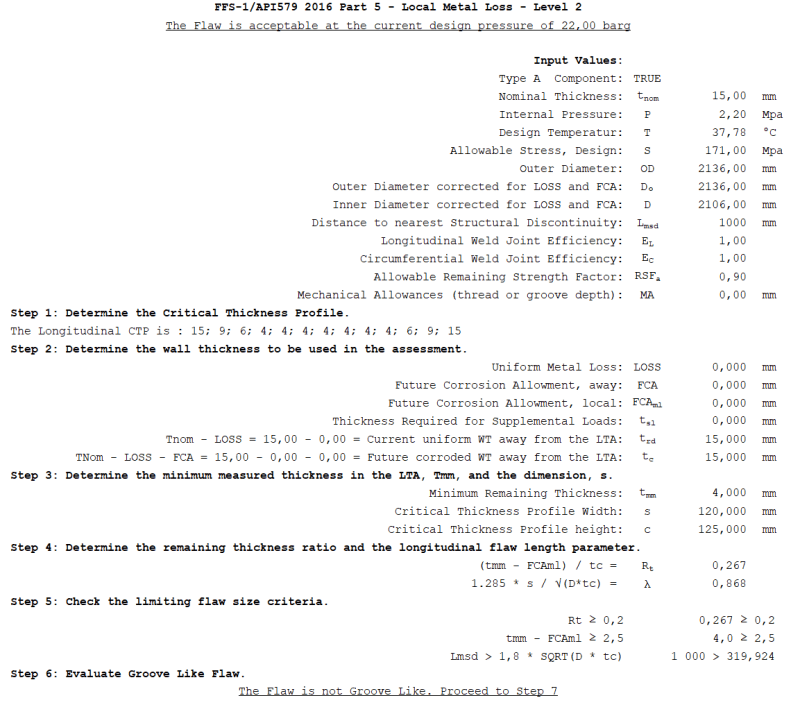
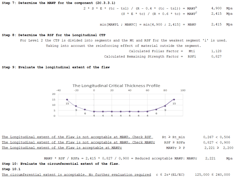
Using tnom 15 mm and S = 171Mpa the vessel may pass a Level 1 evaluation with tmm 6 mm and Ø125mm (external)
Using Level 2 and an assumed CTP I can push it down to tmm 4mm

1a_qdkndr.png

2a_baygie.png


I take no responsibility whatsoever, were you to base your assessment on the provided calculations. Have fun!

1.FFS
2.Re-rate
3.Repair
4.Replace
 
I do not see any problem in carrying out the weld BUILT-UP in PCC-2 2022 article 211 and API-579 2021.

Regards
 
@Bjorn Nilsson - thank you for the assistance. I will review the API 579 FFS information for LTA analysis. The code calculation for PD5500 is slightly different than ASME so the tmin would be a bit different. Of course, anything suggested I will recheck/redo myself.

@r6155 - Yes weld build up also being done at the moment where the metal loss is quite significant.
 
Andrew ONeill said:
Yes the plug welds are there to help with bending loads through the outer weld, but I believe also "help" transfer some of the other loads as well, I've never tried to analyze it before

5) I've usually ended up with a "fillet weld patches don't work" situation on most vessels, in particular vessels with and joint efficiency of 1.0, and minimal corrosion allowance. The end solution for me as been
a) do a full circumferential ring
b) Do an insert plate instead
b) go down the FEA route

With respect to a full circumferential ring, wouldn't the analysis to determine the thickness of the ring end up including the eccentricity check i.e. bending resulting in the same thickness of a fillet patch ?
 
NEVER a full circumferential ring !!

Regards
 
r6155 said:
NEVER a full circumferential ring !!

As this would be essentially a type B sleeve in PCC-2, any particular reason why ?
 
@ NovaStark
Sleeve Type B is for piping.

Regards
 
Status
Not open for further replies.

Part and Inventory Search

Sponsor