Continue to Site

Eng-Tips is the largest engineering community on the Internet

Intelligent Work Forums for Engineering Professionals

  • Congratulations KootK on being selected by the Eng-Tips community for having the most helpful posts in the forums last week. Way to Go!

PEMB: 240k Kickout Tie-Beam 5

Status
Not open for further replies.

UTvoler

Structural
Oct 7, 2010
49
Hi all! I am working on a PEMB with a 200' clear span, with factored horizontal reactions of 240kip at the baseplate. I am really struggling to get this magnitude of a shear reaction into the the pier and then transferred into the tie-beam. To make things extra fun, I have two frames where my tie-beams will intersect pits in the floor, and so the tie-beams want to drop down 24" below the top of the slab, which makes the pier ACI anchor rod checks impossible without an 8-ft square pier (I also tried the strut-and-tie approach with no luck).

All that aside, my "typical" tie-beam that I am somewhat comfortable with is 24"x16" concrete beam with (12) #10 bars. For various reasons (like welded/mechanical splices, and a slightly questionable approach to lapping the beam bars into the shear cone of the pier) I am thinking of using a concrete encased HP10x42 beam instead of rebar for a tie-beam.

Am I crazy; anyone ever done such a thing? Pro's: I could splice the beam to a setting plate with a heavy bar and hang my hat on the shear transfer; two beam splices in the span is pretty straight-forward; there's not a bunch of rebar to deal with, etc. Only Con that comes to mind is burying a steel beam even though it will be embedded in concrete....not sure why that gives me pause?

Appreciate any thoughts anyone may have!
 
Replies continue below

Recommended for you

Using a tie beam over 200 ft. makes me nervous in that your Delta = PL/AE stretch at 240 kips could be a very large lateral deflection.
...unless of course you pre-tension it somehow but that wouldn't affect the delta, just compensate for it... in that you would have to tension as the building is erected or something to keep the column base in position.

An exterior buttress, or perhaps battered piling or footings might work more directly.

 
240 kips?

I'm a PEMB guy and that sounds crazy. I checked a 200 ft clear span hangar that we did recently and the largest lateral factored load is 74 kips ASD.

So if you haven't already, either question that loading or figure out how it's so large. The biggest lateral loads on PEMBs are due to wind but they're typically due to wind suction on the rafters which means they act inward toward the center of the foundation. For the building I'm looking at the maximum un-factored lateral load that would act outward is from combining live, dead, and collateral load is 26 kips.
 
Yup, I was just about to ask the same thing about the 240k load? How big is the column if your horiz. reaction is really 240k?
 
JAE, thanks for the input...my biggest issue without a tie-beam is the pier and resisting the sliding....I would need batter piles to bedrock.

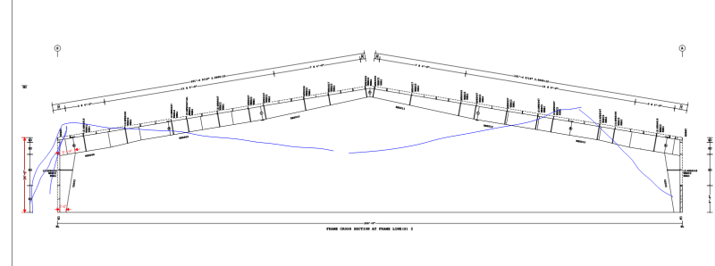
SandwichEngine, I'm still having a hard time processing it as well. Should have clarified; it's 240 LRFD / 164ASD, project is Risk Category III due to occupancy load and the controlling load combination is D+S (moderately high snow at pg = 42 psf) with the thrust equal and outward both ends (50' bay spacing also). But that's a great thought to verify the reactions (why trust the PEMB designer after all); I have a frame set up in RISA so I will run it tomorrow and see if I get anything close to what the PEMB preliminary RXNs are indicating. Typical frame preliminary RXNs attached for your leisure reading...
 
 https://files.engineering.com/getfile.aspx?folder=4b300841-d404-4571-b5d6-8ccc0ae23ba8&file=Monster_Frame.pdf
The PEMB could be in northern MN where the ground snow is 60psf.

Edit: waited too long to post, but not 60 psf.
 
I love the 1:22 AM time stamp on that frame output… guess I’m not the only one.

I would start by looking at a concrete grade beam for a tie with several large diameter rebars or threaded rods. Just ballparking some numbers I get (10) 2.25” all thread bars for ~1/2” total elongation. From there I’d look at the pier dimensions required to terminate/anchor those bars, then probably some kind of embed/weldment to take the shear out the baseplate and into the pier. You could even embed a deep weldment like a WF section that has the all thread bars directly welded via coupler terminations.

The batter pile option seems equally viable, but has its own challenges and not sure if it’s economical vs the tie beams or not.
 
Bones, the design builder's engineer had preliminary tiebeam with (4) #10's, my current design is at (12) #10's. What say you on embedding a wide flange in concrete instead of all the bars?
 
Like a 200 ft long wide flange tie? Sounds like a lot of expensive splice joints. All thread rods or rebar can have simple threaded couplers and are pretty conventional construction for tie beams. I’m always open to outside the box ideas but I’m just not seeing any real advantages of using WF for the tie.
 
I'm a little more friendly to the embedded WF concept. Things I like:

1) Might be easy to grossly oversize the member for stress such that it is suitably sized for elongation per JAE's comment. If the thing stretches appreciably, the PEMB design will probably be invalid.

2) The splices should be easy to do and, moreover, might be convenient places to prestress the tie using the splice bolts.

3) If this makes problems go away at the connection to the column base, as you say, that would be a huge benefit.

4) If you're going to dance the ties around some pits, the detailing of that might be more convincingly done in steel. This, particularly given that code requirements probably will steer you towards mechanical splicing which will make an offset lap splice between high and low ties a bit dubious.

Like bones206 has intimated, I suspect that there are ways to accomplish all of these things with thread bar. I'd be inclined to work through the detailing implications of both solutions en route to making a recommendation and, ideally, get some contractor feedback on both options.


JAE said:
Using a tie beam over 200 ft. makes me nervous in that your Delta = PL/AE stretch at 240 kips could be a very large lateral deflection.

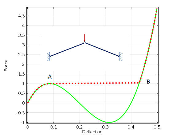
I do feel that is a very important aspect of this at the scale being contemplated. At the risk of being alarmist, it raises the specter of snap through buckling for me. I think that's a pretty unlikely outcome in any case but, man would it ever suck if it came to pass.

c01_y00kp1.png


c02_smbrke.png
 
There are few better ways to a quick headache than trying to decipher PEMB output files.

Anyway, I took a quick look at the reactions on the sheet you attached above and have a few comments:
[ol 1]
[li]Based on the frames being spaced 50' on center as you stated above, I assume that means the tributary area for the vertical column reactions shown on that sheet is 50' x 100' = 5,000 SF. Based on a ground snow load of 42 psf, for a 2:12 pitch roof, Building Risk Category III, and assuming Ce and Ct are both 1.0 (which might be a non-conservative assumption), I get a sloped roof snow load of 32.34 psf. Based on our tributary area, the vertical column reactions due to this snow load is 161.7k. I'm not sure where they got the 92.03k.[/li]
[li]Whoever is running the loads on this should also be accounting for unbalanced roof snow loads. I would guess that's what the "S>" and "<S" loads are supposed to be for, except that the reactions don't make sense in that case. With the unbalanced snow loads, you would obviously have different vertical reactions for the two sides.[/li]
[li]I assume the total dead load is the sum of "CG" and "D". That makes sense in terms of the load magnitude.[/li]
[/ol]

If the loading is wrong, you should get that ironed out first. For PEMB projects like this I usually spend a little time looking at the loading and reactions to make sure it's somewhat sane.
 
Just a quickie calc - assuming the following:
P = 164 kips (service)
L = 200 ft.
A = 8 sq. in. - based on a rough 0.6Fy limit on stress for 164 kips
E = 29,000 ksi

Delta = 1.69 inches - possibly half and half each column = 7/8" deflection each column so not as bad as I imagined.


Whoops, didn’t pick up on the LRFD part and did my previous elongation calc for the full 240k, which required about 39 sq in of steel for 1/2” stretch. For the 164k ASD it would be ~27 sq in for the same 1/2” stretch limit. Btw the 1/2” limit is just my personal rule of thumb for these. I’m sure most frames can tolerate a bit more, but I’d rather not eat too much into the reserve capacity (if any).
 
All, thanks very much for the input and responses. I checked the loading/reactions, and I think what the PEMB designer provided is probably good (although I did mis-speak after banging my head all day yesterday; the max bay spacing is 25'-6" not 50'). I have set a max elongation as 1" (using ASD reactions) for ~0.5" per column, and after thinking thru some connection and other details would size the rebar/rods to be (4) bars to fit within the concrete and to limit the mechanical splices etc. I'm still leaning a little more towards the embedded WF idea, mainly for the connection to baseplate and the two lines where I have to deal with dropping under the pit (see sketch). The other option there is to drop the tiebeam to the top of footing, but then the concrete pryout/breakout in the pier is almost insurmountable. Although maybe I just embed a steel column to underside of setting plate there.
Anyway, I'm about to start bouncing some of these options off the contractor (who already thinks I'm crazy) so the fun will continue! Thanks once again!
 
 https://files.engineering.com/getfile.aspx?folder=8a16329a-2370-4296-99bd-8f13f8f0fbcd&file=X-SECTION.pdf
utvoler said:
Anyway, I'm about to start bouncing some of these options off the contractor (who already thinks I'm crazy) so the fun will continue!

Make sure that the contractor knows that a 200' clear span is not a typical situation. I know the solutions to handle this much thrust seem "crazy", but 240k (ult) is certainly outside of the typical PEMB box (at least where I'm at in the Great Plains region). It's not your fault the owner doesn't want any interior supports, and all the "crazy" is flowing from that decision.

Please note that is a "v" (as in Violin) not a "y".
 
Not sure if anyone will see this continuing the conversion in an old thread but here we go....the Contractor's PE offered to review my tie-beam calcs, which I took him up on. He came back with the suggestion that the 110k (ASD) thrust reaction due to snow would not contribute significantly to the elongation of the tie-beam and could be ignored due to it being a "short duration load"; his experience over his 42 year career is that elongation is not an issue...Yikes.

He also indicated his design approach was to determine how much thrust could be resisted by the cantilever foundation, and then resist the "additional" tension with a tie-beam. I considered this early on, and disregarded it because I didn't see how that could work. Due to the extremely large thrust load, I detailed a weldment to create a direct connection from the PEMB base plate to the tie-beam reinforcing. It seems to me that the tie-beam would have to undergo some elongation to engage movement of the foundation to get any resistance from passive and sliding friction. I can maybe see it with my second detail (see attached) where the tie-beam is at the top of the footing.

Anyone have an opinion; can the thrust be resolved by a combined resistance? Thrust = tie-beam + sliding + passive?
 
 https://files.engineering.com/getfile.aspx?folder=53088367-de2f-4ef3-84e2-8895859c0a06&file=S6.01.pdf
utvoler said:
Anyone have an opinion; can the thrust be resolved by a combined resistance? Thrust = tie-beam + sliding + passive?

You could, but only if you can accurately assess the relative stiffness of those sources of resistance. A failure to consider deflection compatibility is just wishful thinking.

And yeah...saying you don't have to resist snow load is irresponsible and dangerous.

EDIT: Just noticed you're in Virginia, too. I really want to know who these parties are...
 
That is tricky. It depends on how much elongation you expect from your ties. If you have 0 deformation then yes, all forces are internalized within your tie rod and column system.

However, if you expect any more than 1/8" of elongation then I see it as follows:

1. In order for your ties to engage they have to begin deformation.

2. In order for your passive cone to engage, there needs to be tiny amounts of movement, which tracks with point #1.

3. In order for the friction to engage, you need to NOT be moving. However, as the snow load increases the foundation would be "Creeping" out... So to me, that is having static friction at any instantaneous point that could be added to your capacity. I can buy that and add it to point #1 and #2.

I disagree that elongation isn't an issue per the peer review comments, but I can buy the argument that all three act together. Now modeling how each of those interact with each other is a different story...

EDIT: I think that static friction is directly additive to the tie rod load required with no stiffness check required. I would take this route and ignore the passive soil cone as it would be too difficult to accurately predict, but you know that it would be helping you. Seems like a nice compromise to me. Plus, whenever you push the passive soil cone out once, and you "shrink" back in after the load is taken off... Your soil is no longer as compacted or resistive to being pushed out in a passive manner again.
 
Status
Not open for further replies.

Part and Inventory Search

Sponsor