Eng-Tips is the largest engineering community on the Internet

Intelligent Work Forums for Engineering Professionals

PEMB: 240k Kickout Tie-Beam 5

Status
Not open for further replies.

UTvoler

Structural
Oct 7, 2010
49
0
6
US
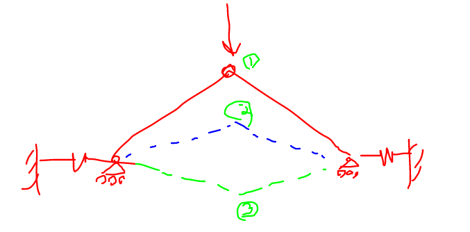
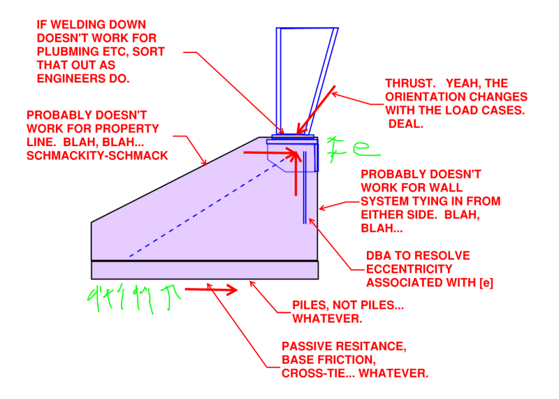
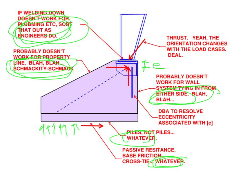
Hi all! I am working on a PEMB with a 200' clear span, with factored horizontal reactions of 240kip at the baseplate. I am really struggling to get this magnitude of a shear reaction into the the pier and then transferred into the tie-beam. To make things extra fun, I have two frames where my tie-beams will intersect pits in the floor, and so the tie-beams want to drop down 24" below the top of the slab, which makes the pier ACI anchor rod checks impossible without an 8-ft square pier (I also tried the strut-and-tie approach with no luck).

All that aside, my "typical" tie-beam that I am somewhat comfortable with is 24"x16" concrete beam with (12) #10 bars. For various reasons (like welded/mechanical splices, and a slightly questionable approach to lapping the beam bars into the shear cone of the pier) I am thinking of using a concrete encased HP10x42 beam instead of rebar for a tie-beam.

Am I crazy; anyone ever done such a thing? Pro's: I could splice the beam to a setting plate with a heavy bar and hang my hat on the shear transfer; two beam splices in the span is pretty straight-forward; there's not a bunch of rebar to deal with, etc. Only Con that comes to mind is burying a steel beam even though it will be embedded in concrete....not sure why that gives me pause?

Appreciate any thoughts anyone may have!
 
Replies continue below

Recommended for you

bones206 said:
but I know a lot of engineers utilize it.

Guilty. But only to control anchor shear/concrete edge failure. Never use them for resisting MBS thrust.

Granted...with these loads...I'd certainly think twice even for that.
 
Aesur: if you scroll back up to 4 Nov 23 22:11 you'll see my two details I uploaded at the pier. The pier doesn't have to be above slab; it has to be at it. I have a weldment where the ties are up near the slab, and a WF column very similar to your sketch (you have to look for them; they're detailed elsewhere) where the tie is down at the top of footing and both are encased in a pier (which I can't really tie per ACI; another source of heartburn for me). Great minds think alike!

Aesur/bones206/WesternJeb/phamENG: I have #6 hairpins at my frames w/o tie beams, because why the hell not? But I also have thrust from wind in the opposite direction towards the building, which is also massively obnoxious. For all the obvious reasons/concerns, I'm reluctant to count on hairpins for anything other than suspenders which takes me right back to ACI/STM to justify getting the thrust into these piers where I don't have ties. Maybe the obvious solution is to use the same weldments/stub column/ties on those as well....

Hope you guys don't think I'm poo-poo'ing your thoughts/ideas, because they are much appreciated!
 
@utvoler - I see your PDF now, I missed it when scrolling through. The main difference between our details is I would connect the tie beam to the WF column and drop the footing to avoid needing to use anchors for moment transfer to the footing, although I'm sure there is an option that works as your detail shows it.

At this point, the only option you have is to provide something that works and don't worry about what the contractor thinks, their prelim engineer as you noted, should have caught this.
 
I'm losing track of this, what is not working at this point? The anchorage into the pier?

What about a zip code for the property? I haven't done much design in Tennessee (I inherited something under construction in Hendersonville, which happened to develop a "crack down to the center of the earth" when it was supposed to be more or less on bedrock), so I don't know how critical location in the state is for snow load, but it sounds high (I deal with 50 and 60 psf ground snow loads typically but I'm way north of TN).

I keep coming back to the snow, because I guess, nobody has yet said it's a wind load that's causing this large horizontal reaction. To me, it seems possible there's a reduction in the snow load (or two, no, wait, three, AAAAAHHHHH) that are not being considered, and given the large load, anything to cut down on the load reduces the horizontal reaction. Maybe I'm just locking into something irrelevant, but as it states in ASCE 7, "fully exposed" site with a sloped roof can use a Ce = 0.9 for snow, if in Exposure B/C and 0.8 if Exposure D (I suppose pretty low chance of a "salt plain" in Tennessee), Table 7.3-1 ASCE 7-16, and the Ct = 1.1 for higher thermal insulation is for ventilated roofs, (Table 7.3-2) which I suspect a PEMB would not be ventilated.

If we get more ambitious, the unobstructed slippery surfaces start getting Cs reductions above 2:12 roof slope. This building seems to be oddly "high slope" for a PEMB (i.e. > 1/4" per foot).

As a side note, unbalanced snow doesn't apply to a "typical" PEMB due to slope of 1/4" per foot (it applies between 1/2" per foot and 7" per foot).

This lateral load makes me think of some kind of almost retaining wall.
 
Great news everyone, the Contractor has fired me! They are going to have their (soon-to-be-retired) in-house PE take over the design of the foundations for this project! Never been so relieved to be fired in my life....guess they didn't like (and couldn't afford) my design compared to the way their PE "has always done it".

I very much appreciate everyone's thoughts, comments, and input. While this has been a black-hole of my time, it has certainly been a great refresher on digging thru ACI code and (attempted) problem solving for an extremely challenging design.
 
Ah, well. You can always be the expert witness for the future Owner.

This is part of the reality of being a structural engineer, "fast" means you are good and know what you are doing, "slow" means you probably don't know what you are doing. Speed is misconstrued as competence.
 
WinelandV said:
Bypass ACI 318 Anchorage provisions and size & reinforce your piers such that they fall within STM analysis. Pretty sure Koot has good thoughts on this approach.

Indeed I do. This isn't what you will have had in mind but it is STM informed none the less.

One of the things that I find frustrating about these things is that they would seem to suggest an obvious structural form which always gets vetoed for some annoyingly practical reason. These things are basically three hinged arches. So give them what most three hinged arches have: thrust blocks. Solve the shear anchorage problem by arranging the concrete to receive the load in compression bearing instead of shear, as concrete is meant to do.

Yes, I realize that the odds of this solution coming to pass for OP are -20% +/-. KootK no care.

image_n4ast8.png
 
FWIW I'll repeat my prior statement that I stopped worrying about snap through back when JAE generously posted his elongation numbers.

lexpatrie said:
Koot - what I was getting at is the stiffness of the support plays a role in the snap through doesn't it?

Indeed it does. Stiffness tends to be THE thing for most forms of buckling. That's why I said this previously:

KootK said:
I abandoned snap through once I saw how small JAE's elongation numbers were.

Those elongation numbers, speak to stiffness.

lexpatrie said:
If the knee/knuckle can't offer much stiffness versus the spread?

This just speaks to hierachy of failure in my mind. Maybe everything is stiff and snap through happens at a very high load. Maybe the bases are laterally soft and that causes snap through at a lower load. Maybe the knuckles are soft and that causes snap through at some load that is more or less than the other versions...

See the 1st sketch below for an example of a situation in which a lack of knuckle stiffness might encourage snap through buckling.

lexpatrie said:
I mean if there's no rigidity at the supports it's a mechanism but the snap-through doesn't happen?

I didn't say no rigidity. Rather, I spoke to lateral base flexibility. See the 2nd sketch below for an illustration.

c01_npxgb8.png


c02_twqizs.png
 
I'm not sure, now that I think about it more, the compression in the elements is (to me, perhaps) the source of the buckling, so the stiffness of the support changes the angle of the rafter but it doesn't change the force all that much, so support stiffness or lack thereof doesn't alleviate the potential for snap-through. I was just trying to bound the solution between rigid and sliding to try to grasp the potential behaviour.

As to the foundation "cure", if it's a PEMB those tend to be on fairly large sites, so you might not have a constrained lot you are dealing with, and even so, the original design had a spread footing under it, which implies it's not built to the lot lines, so it's an artificial constraint you added that's not in the problem statement. It could apply to other situations, but not this particular one? Looks thematically similar to a counterfort retaining wall.

I'm a bit sad this project sort of died, because it was generating some interesting ideas. If everything can be adequately tied together, with a bay spacing of 25'-6" there's potentially 25'-6" of wall/stem/continuous footing one could engage, half on each side of the column. It's perhaps not entirely realistic to try to push that much soil (plus, I suppose one side of soil opposes, the other side pushes it along), it starts to turn into more and more of a retaining wall.

As to the anchorage/force transfer at the steel/foundation interface - Newman does show a plate and welding (I think at least partly because the anchor rods in bearing need a lot of movement) as an option there, so it's not unheard of. I feel like the anchorage can be gotten to work, but the pier cross section needs to be good for the shear as well, plus the joint with the footing.... there's a lot going on here.

Regards,
Brian
 
lexpatrie said:
Looks thematically similar to a counterfort retaining wall.

Yes, that's almost exactly what it is.

lexpatrie said:
...so it's an artificial constraint you added that's not in the problem statement. It could apply to other situations, but not this particular one?

Also yes. You may have noticed that, in my sketch, I was a tad cavalier about some of the particulars. See below. That was deliberate and represented me:

1) Focusing on that part of the solution that I felt was most salient (counterfort) while leaving the particulars to OP's discretion.

2) Acknowledging the factors that I know typically impact decision making in these situations. That, for the benefit of readers that we will refer here in the future.

Bones206 said:
Well... you could use a large hairpin that extends out into the slab to get the development length required for a larger diameter bar. I'm not big on that approach, but it is something people do.

I see that comment as having likely been made in a similar vein. Bones knew full well that he was going to draw criticism for that for all of the technical problems that most of us know plague that solution. That said, in many markets, the hairpin solution will currently be the solution that comes to pass, despite its shortcomings. We would be remiss to not mention that for the benefit of future readers of this thread struggling with their own versions of this issue. We don't want to, spuriously, give anyone the impression that it's "just them" and that this kind of work is not fraught with obnoxious compromise.

c01_eascsf.png
 
lexpatrie said:
I'm a bit sad this project sort of died, because it was generating some interesting ideas.

Fear not, it doesn't die it just morphs....

bones206 said:
Yup. Despite the crowdsourced effort, we basically all got fired from this job

Stings, doesn't it?

I'm not completely fired; my scope has been reduced to the mezzanine structure design. I am wrestling with whether I want to be associated with this project at all at this point...probably the topic for a new thread, but what do I do if see the final foundation design for this building look anything like the preliminary design (attached) that was provided by the GC's PE (who has 40+ years of PEMB foundation design/structural experience)? Is there risk to the safety, health, and welfare of the public; is there an obligation to report my concerns to the Authorities?
 
 https://files.engineering.com/getfile.aspx?folder=23cfbd9d-c01b-47da-809b-53ccf770789f&file=FTG_DTL.pdf
Yikes. I think I would bill them for my time, and decline to do anything for them. Hopefully once this guy goes beyond 'preliminary' he'll realize he needs something more...
 
The problem with 40 years experience, is that experience predates a lot of the current code requirements for anchorage in concrete. I tend to see a some willful ignorance associated with that particular aspect of design. That preliminary design looks a bit scary. Hope they know what they are doing...

portland-press-herald_3522193_dm7t1p.jpg
 
I agree with phamENG. I would send the final bill and politely decline any future work with them.

I would give the other engineer the benefit of the doubt on this and wouldn't be looking for issues, but if you were made aware of negligence, you should report it.

I never know how to feel about projects like this. It seems that we spend all this time trying to do things right, follow the code, etc. but as soon as there's another engineer who can provide an easier/cheaper solution for the client, they will always be preferred over us. Maybe the other engineer really does have a better solution that's also code-compliant, but I doubt it. It's likely more along the lines of: "I've been doing these building for 40 years, and all we need is a few hairpins at the column locations." To me, 40 years experience can often mean somebody learned how to do something one way 40 years ago, and that's how they always do it now.

On the bright side, though, some engineers would say the best projects are the ones that never get built.
 
I'll add a final note, if you are aware of the challenges, you're in the zone of "seeing your engineering decisions overridden by non-engineers" (I know, there's a replacement engineer. It's their problem. They need to practice in their area of competence. I grant that, however, still. Continue or withdraw, I would inform the "replacement" engineer of the concerns you had with the design and the lack of viable solutions, per your experience.
 
lexpatrie said:
I'm not sure, now that I think about it more, the compression in the elements is (to me, perhaps) the source of the buckling...

I disagree that high compressions are the impetus for buckling with snap through problems. Snap through problems are about the geometry of the setup being such that the stiffness of the system decreases with increasing deformation and, eventually, turns negative.

Considering the sketch below, I feel that it is accurate to say that:

a) Although the presence of the lateral springs would reduce the pre-buckling compression in the frame, they would not preclude buckling of the frame.

b) If anything, the presence of the lateral springs would facilitate snap through buckling at a lower load than would be the case if the springs were absent.

The relevance of this to OP's frame is the impact that it could potentially have on the 240K tie tension. I'm guessing that's the value associated with pinned supports at the column bases. When the column bases move laterally, as they will, that 240K value will increase. At it will be primarily the stiffness of the tie that keeps it from increasing catastrophically.

At the start of the thread, everyone had sticker shock at that monstrous 240K tie value. That value was as high as it was because these frames are fundamentally three pinned arches. And, for a given height, a very long frame is, effectively, a very shallow arch. It's reasonable to expect that shallow arches develop very significant thrusts at their bases.

c01_dmakpg.png
 
Status
Not open for further replies.
Back
Top