Continue to Site

Eng-Tips is the largest engineering community on the Internet

Intelligent Work Forums for Engineering Professionals

  • Congratulations SSS148 on being selected by the Eng-Tips community for having the most helpful posts in the forums last week. Way to Go!

PEMB Wind Post Bracing 2

Status
Not open for further replies.

XR250

Structural
Jan 30, 2013
5,953
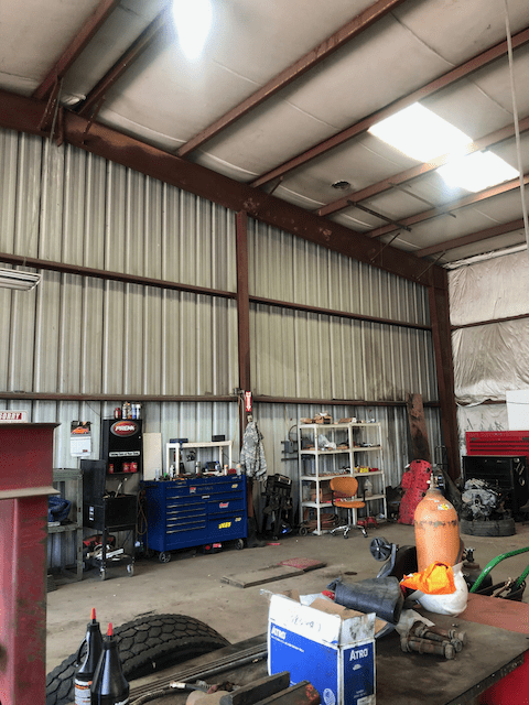
Saw this the other day while getting some tires. The post is about 20 ft. tall and has 20 ft. span girts +/- on each side. Seems like that tiny brace from the bottom of the end frame to the purlin is pretty optimistic for transferring the out-of-plane post load into the diaphragm. Seems the purlin would not be too happy about it either.
IMG_1844_uljmy9.png
 
Replies continue below

Recommended for you

human909 said:
The problem is that for this load path to work then the torsional stiffness of the roof beam needs to be significantly greater than the torsional stiffness provided by the fly brace. (which it almost certainly isn't)

Thus the fly brace would become part of the load path of the end wall wind load whether it was designed that way or not.

I agree. I bet you $1 that the roof beam does have near the stiffness, let alone, the capacity to resist the wind post reaction. Honestly, I used to see these shenanigans frequently when I was doing CFS design. Let's span a W12x14 24 ft. along an eave and then attach 12 ft. long metal studs to the bottom with slip connections.
 
Hi, guys, I see purlins, fly braces, joists, bracing rods, where is the BEAM in the conservations?
 
retired13,

Read again. It is there. Many of us call it a rafter, but sloping BEAM will do.
 
I see. The conversation has swing back to the original photo. Thanks.
 
I feel like I'm logging into this account more than my main! Once again, licensed PE/SE working for one of the big PEMB manufacturers. I figured I'd help try to give some light on how the purlins were likely designed.

The fly brace is how the load is going to get up into the purlins. As mentioned, it's much stiffer than trying to pass it from the bottom flange of the column up to the purlin sitting on top of the rafter. It's one of those things that's missed a lot, but for tall enough buildings, or those with enough wall trib, I will upgrade size/bolts of those connections to ensure it can adequately transfer the load into the purlin.

The purlin itself is (or at least, should be) designed for the extra axial load. By analysis, it's likely that wasn't too much, or else an additional compression strut member (likely cold formed material) would be supplied to help transfer the load into the bracing truss system that I assume is located outside the picture.

I'm guessing the roof deck is a through-fastened system; as everyone mentioned there's no discrete bracing to the purlin bottom flanges. AISI S100 sets the capacity of the section with an unbraced compression flange (uplift) as a percentage of the capacity of loading in the other direction (gravity), based on depth and profile of the shape. This is checked with combined loading from axial, and the gage of the purlins along the strut lines may be increased, depending on how far the load needs to strut to the roof bracing.
 
Thanks for your insights, AE
 
XR250,

Can you provide better pictures of the entire frame in question and closeup detail pictures of the top of column connection to the bottom of the roof beam and endwall girt connections to the endwall column?

I feel like we are being asked to provide solutions to questions when we are five blind engineers standing around various parts of an elephant and not alowed to see the entire elephant.

I agree that the roof beam is not torsionally stiff enough to resist the endwall wind loads, but the column connection and any roof beam stiffeners along with flange braces/fly braces provide adequate stiffness to get the endwall wind loads into the roof structurals (purlins) axially.

I have never seen a roof structural failure like the one shown in the second picture, but it looks like a local buckling issue as most of the purlins failed approximately the same amount and not in varying amounts as they would have with axial bracing loads which would be additive down the roof slope and the largest loads in the strut purlins at the brace rod connections to the frames. Since we can't see the connections of the purlins to the roof beams we can't tell if the the struct purlins have heavier connections.

Jim H
 
Jim, that is the only pic I have. It was just out of curiosity and not a project for me.

Your recent statement seems to contradict your previous one....

"The tiny fly brace/flange brace (you mentioned) serves to provide bracing to the bottom flange of the roof beam in the compression areas of the roof beam and not to transfer endwall windload to the roof structurals (purlins). Most of the endwall wind load is transferred to the roof stucturals by the purlins bolted to the top flange of the roof beam. There are normally a variety of connections available to transfer the wind load from the roof beam to the purlins."

Thanks.
 
"The tiny fly brace/flange brace (you mentioned) serves to provide bracing to the bottom flange of the roof beam in the compression areas of the roof beam and not to transfer endwall windload to the roof structurals (purlins). Most of the endwall wind load is transferred to the roof stucturals by the purlins bolted to the top flange of the roof beam. There are normally a variety of connections available to transfer the wind load from the roof beam to the purlins."

In my opinion, this is accurate statement about the primary role of the fly brace.
 
XR250,

Have you actually seen that endwall frame in its entirety or are all your questions based on what is visible in the first picture?

The flange brace (Butler's nomenclature)/ fly brace primarily serve to transfer/provide flange bracing in the compression flange areas of the roof beam/ rafter beam (or column if present) of the frame. I would also guess that some transfer of wind load also occurs.

Remember these buildings are structural systems, all of which must be present and properly functioning for the building to be successful in supporting the loads in a full design event.

Jim H
 
Status
Not open for further replies.

Part and Inventory Search

Sponsor