Eng-Tips is the largest engineering community on the Internet

Intelligent Work Forums for Engineering Professionals

PERMANENT MAGNET GENERATOR DESIGN-TO AVOID COGGING

Status
Not open for further replies.

Ethnan

Electrical
Mar 13, 2020
48
0
0
NG
Hello Everyone,

I need information on how to design a PM generator and have the rotor turn freely, without too much cogging from the forces due to the strong neodymium magnet.
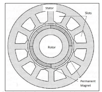
I have several diverging information from my research and need to be sure of what I am doing. Generally, there seems to be a relationship between the airgap, the number of poles, the pole size, the number of slots, slot size and distance between slots, for one to achieve a cogging-free generator.

Please I need some professional guidance. Any useful advice will be highly appreciated. Thank you all.

Kind Regards

PM_Generator-Cogging_q0s10o.png
 
Replies continue below

Recommended for you

I'm surprised you would see diverging information on reducing cogging.

fractional slot/poles, small slot openings, larger airgap, skewing stator/rotor, profiling magnets or magnetization, and dummy slots can all be used to mitigate cogging... slotless stator and airgap winding is the best approach for reducing cogging according to hendershot/miller...

all of these are going to reduce your winding factor, bemf, and/or increase production difficulties.
 
@Onatirec,

Thanks for finding time to respond on this.

I am actually referring to a clear mathematical formula that establishes a relationship between the variables I listed earlier. Increasing the airgap between the rotor and stator will reduce cogging but also the mmf. This is not an option I want. In fact I would want airgap as small as 1mm. Most of the literature on this agree with the variables that can affect cogging, but the exact mathematical relationship is what I need.

Kind Regards
 
onatirec - I recognize your username from machineryanalysis.org where you posted some very interesting vibration readings and analysis for pm motors. Looking forward to more of that.

op - I get the feeling it may seem simple to someone very familiar with it like onatirec but it seems like a broad and somewhat complicated topic to me.
fwiw I googled and found 2 articles that may or may not be helpful

[ul]
[li]Cogging Torque Reduction in a Permanent Magnet Wind Turbine Generator [/li]
[li]Methods to Reduce Cogging Torque of Permanent Magnet Synchronous Generator Used In Wind Power Plants [/li]
[/ul]

=====================================
(2B)+(2B)' ?
 
@ electricpete

Many thanks. Skewing of magnets and stator. "...a perfect skew can nearly eliminate
cogging torque." Rotor magnet shifting angle. Some very good insight.

@onatirec: Any reference literature to read up this assertion? "slotless stator and airgap winding is the best approach for reducing cogging according to hendershot/miller..."

Guys, thank you very much.

 
Back when I was building motors we didn't have detailed models.
It was the pre-PC days.
We used slotless stator lams and we skewed them slightly.
It is much easier to skew the lams than the magnets.
You do lose performance from both but you can minimize it.
Our lams had a very small bridge between poles (highly saturated), the skew was kept as small as possible, and our windings were very tight.
Yes they were a PAI to build.
These motors had a very wide speed range and ran very smooth.
I'll also point out that this was pre-Neo days also.
But it didn't matter.
The units ran hot enough that using Neo magnets would not have helped as Neo has a huge drop in properties with increasing temp.
We were using a 2:17 SmCo grade with about 28MGOe. At 150C it was stronger than any Neo grade and it would work clear up to about 300C.

= = = = = = = = = = = = = = = = = = = =
P.E. Metallurgy, consulting work welcomed
 
Flattered you remember me Pete.

I used to spend a lot more time analyzing motors, but have been too bogged down in pm motor design to do that for a while now.

Cogging arises from the non-uniform permeance the rotor poles see as they rotate relative to the stator. The permeance in the magnetic circuit is much higher when a pole is directly across from a tooth, so these are the positions that the flux prefers. With that in mind, it's only a small jump to see how all the factors I mentioned help smooth the permeance / flux linkage, and it's almost trivial to say that removing the stator teeth (slotless motor) must be the most effective way of removing cogging.

That said, skewing the stator is a commonly used, good approach that doesn't hurt performance too much. But it's really not enough without other good design decision. Slot/pole combination is important. Generally you want to increase the LCM of the slot/pole count, without adversely affecting the winding factor too much. You can find tables of winding factors online. Probably an 18/14 motor is a somewhat better choice than the 12/8 shown in your picture... Similarly, I'm not sure surface mount is as good as IPM for cogging torque.

You can find discussions in e.g.:

Libert, Soulard - Investigation on Pole-Slot Combinations for Permanent-Magnet Machines with Concentrated Windings
Henderson, Miller - Design of brushless permanent magnet machines (The PM machine bible)

You might underestimate how messy and complex the relationships are, but you can find equations in:
Timar - noise and vibration in electrical machines
Gieras - Noise of Poylphase electric motors
Besnerais' Dissertation - Reduction of magnetic noise in PWM-supplied induction machines

Most of the literature I'm aware of on motor vibration is geared toward induction machines.

There is also torque ripple to consider, of which cogging torque is one component.
 
Thank you very much EdStainless and Onatirec. Your posts have been very helpful.

I appreciate this! I appreciate your time everyone.

Kind Regards
 
Status
Not open for further replies.
Back
Top