Continue to Site

Eng-Tips is the largest engineering community on the Internet

Intelligent Work Forums for Engineering Professionals

  • Congratulations SDETERS on being selected by the Eng-Tips community for having the most helpful posts in the forums last week. Way to Go!

Perpendicularity And MMC 2

Status
Not open for further replies.

Alan Lowbands

Aerospace
May 17, 2017
274
Hi,
I was hoping someone might be able to help.

I have just received a report and can't understand how the perpendicularity tolerance was calculated using MMC.
There are two diameter measurements reported, one is stated 'mated' and used for the perpendicularity tolerance at MMC.
The other diameter measurement is different.

Does anyone know which of the two measurements are correct and how the 'mated' measurement is achieved ?
I was wondering if it's software generated but unsure.

I have attached a screen grab.

Any help would be really appreciated

best regards
Alan

 
 https://files.engineering.com/getfile.aspx?folder=33dea6b2-164a-4922-b1d2-14f58912918b&file=Capture10.JPG
Replies continue below

Recommended for you

drawoh said:
I had problems with that one too. This is a hole. MMC/MMB is 90mm.
Ok, so where it is my mistake then?
What should I understand? Do you agree or disagree with me?
 
drawoh,

I think the issue lies with the ambiguous labeling of the measured diameters. There is a "mating diameter" and just "diameter" on the report. If we assume that the mating diameter is the UAME then the calculations are correct, as I assumed in my first post (9 Jul 20 12:10). If instead the 90.170 diameter is the UAME then the calculations are incorrect as greenimi is assuming.

Without clarification from OP and their inspection team then we can't really know for sure. I tend to believe that the 90.075 mating diameter is the UAME though, as you are assuming. That said, if 90.170 is something else for example the maximum measured diameter at any one section, thats quite a bit of form error.
 
hi all,

Datum C is the top surface/plane of the hole.
this should be parallel to Datum A which is the bottom face of the casting.

It seems that this surface (Datum C) has an error and isn't parallel to Datum A.
Errors on Datum C are the surface tolerance of 2.00 A-A which is out of tolerance by 0.448 and a parallel tolerance of 0.8 A-A which is out of tolerance by 0.531
not sure if this helps any ?

thanks guys

alan
 
It seems that this surface (Datum C) has an error and isn't parallel to Datum A.

This has no effect on any tolerance held to only |C| as the FCF's in your report show.

Errors on Datum C are the surface tolerance of 2.00 A-A which is out of tolerance by 0.448 and a parallel tolerance of 0.8 A-A which is out of tolerance by 0.531
not sure if this helps any ?

Aside from not knowing what you mean by the notation A-A (maybe just "with respect to A"? I would just say "wrt A" not whatever this dashed notation is), it does not help for the reason I just stated above.

In fact it raises more questions. I'm not sure how the profile variation of a flat surface C measured to A another flat surface (0.448 - held in location/orientation) could be less than the parallelism variation measured to A (0.531 - held in orientation only).

The only thing in my mind they need to answer is what I asked previously:

Is the "mating diameter" the RAME or UAME? What is the other diameter just reported "diameter"?
 
Thanks chez311,
You can see why I’m struggling with this.
Things don’t seem to make a lot of sense.
 
No worries - I understand the material/concepts can sometimes be tough. It certainly makes it tougher when you don't get the right information from the people doing the measurements.
 
Alan Lowbands said:
Errors on Datum C are the surface tolerance of 2.00 A-A which is out of tolerance by 0.448 and a parallel tolerance of 0.8 A-A which is out of tolerance by 0.531

chez311 said:
In fact it raises more questions. I'm not sure how the profile variation of a flat surface C measured to A another flat surface (0.448 - held in location/orientation) could be less than the parallelism variation measured to A (0.531 - held in orientation only).

Don't these number mean that the surface profile measured value is 2.448 and that the parallelism measured value is 1.331?
 
pmarc,

Yes good catch I guess I read that too fast. I totally skipped the "out of tolerance" part.

So I guess the part was non-conforming to begin with, but it doesn't answer the other questions about the diameters.
 
Hi,

I finally got an answer from the company who did the report and they confirmed that the standard is ISO.
They also said the report was correct.
I'm not so sure as I can't duplicate the result in CAD

Am I missing something ?

regards
Alan
 
Alan,

You're not missing anything. I don't see how you or anyone else could do any kind of real analysis on the results without knowing exactly what boundary / envelope the values represent.

Have they refused to answer the question I posed about what the values labeled actual mating and simply diameter actually represent? Once again without this I can only guess.

I was initially inclined to believe the report was correct. I am less confident about that if they are unable to answer such a simple question.
 
chez311
I agree with what you say.
All I got back was the standard and that the report was correct.
:(
 
I am amazed how complicated mechanical inspection has progressed the last 40 years, a simple perpendicular verification.

Jacob Cheverie (Aerospace)
9 Jul 20 11:13
Alan,

My initial assumption would be that both measurements are "correct", with the non-mating diameter representing the UAME (unrelated actual mating envelope) and the mating diameter representing the RAME (related actual mating envelope) as measured while constrained to primary datum C.

I am always learning thank you all for that, I had educate my self on the terminology and the applications.
as an old mechanical inspector, Machinist, and now as an engineer I would try to simplify geometrical callouts.
an if one method of inspection failed I would reverify it 3 times until I would get the correct measurement.
then I would re-checked it with an other method until I was satisfied with the results. the inspection supplier is not being customer service orientated.
I would contract a third party and have them re-verify to the requirements. and the requirements the specification should be clearly stated on the drawing.

clearly if the mfg and inspection are being confused by a simple perpendicular verification then it needs to simplified. and the requirements
clearly stated. who mfg the part how did they verify the perpendicularity requirement. what is the mating part diameter?
what is it size, can a simulated gage be manufactured so that it can be a go and no application. if diameter is in size
a functional gage fits it's in tolerance. if it does not, then it has failed. keep it simple as possible.
I having difficulty under standing why a CMM can not clearly inspect this diameter with both UAME & RAME and clearly specifying so.
sorry if I come out as an old arrogant dude, but my job over the years was to explain and clarify issues such as this.
thank you
 
pmarc and Chez311,

I would like to ask this question (only for my ISO's lack of knowledge): if bonus does not exist in ISO and the MMVC is the only thing that cannot be violated then why this part is not accepted (considered good)
MMVC is 90.000. Am I correct?
If yes, both measurements 90.075 and 90.170 are bigger than MMVC and they do not violate this boundary (it is an internal feature / hole, as described above)

I am sure I am missing something, but I really do not know what. Could you shoot some light into my own created conundrum, please?

Thank you very much

 
greenimi,

Unless ISO is so radically different, I have to assume that the MMVC is basically oriented to your datum features for an MMC perpendicularity tolerance so that our RAME* must be larger than our 90.000 boundary.

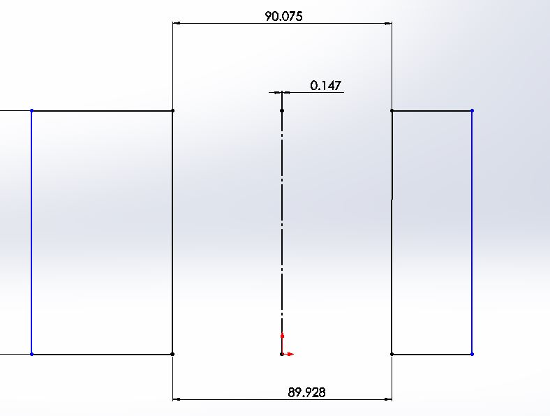
I too have limited ISO knowledge, but even if they don't have the concept of bonus tolerance the calculations should give you a good idea of whats going on in relation to the as produced feature axis. If we assume the 90.075 is the UAME* size and 0.147 is the perpendicularity error of the UAME*, then modeling it out in CAD I get a RAME* of approximately 89.928 which violates the 90.000 boundary. If instead we assume the UAME* size is 90.170 with the same amount of perpendicularity error, then we get a RAME* of 90.023 which would pass. This is why its important to know which is which.

pmarc - feel free to correct me if I'm off base here.

*Or their ISO equivalents. Obviously there is some difference here depending on how the envelope is extracted, the ASME envelopes are strictly outside the material while their ISO counterparts might be partially inside the material with a least squares or similar fitting algorithm.
 
Hi all,

ISO BS.8888 does use bonus tolerances.

Chez311
Could you show me a grab of how you applied the perp tolerance in cad please.
I've tried to draw it up and got the same 90.023 but thought I had done it wrong as it didn't tally with the report 90.075.
I'm still not sure I've done it correctly.

thanks
Alan
 
Alan,

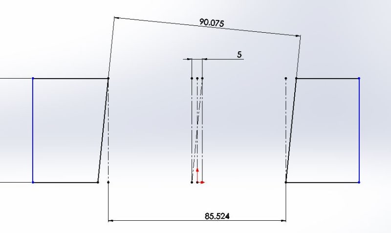
It all hinges on what you assume to be the UAME. If the UAME is 90.075 your RAME is 89.928 (fail vs MMVC=90), if the UAME is 90.170 your RAME is 90.023(pass vs MMVC=90). I didn't include the CAD models because the ratio between the diameter and tolerance zone/orientation error is so high you can't see whats happening without zooming in really far. I included an exaggerated orientation error example at the end to show you what the dimensions are actually attached to.

UAME = 90.075
iso_envelope_jezuus.jpg


UAME = 90.170
iso_envelope_2_taedjl.jpg


UAME = 90.075 but ***ORIENTATION ERROR IS EXAGGERATED AT 5.000 INSTEAD OF 0.147**
iso_envelope_3_f2vofn.jpg
 
OP said:
ISO BS.8888 does use bonus tolerances.

I would argue that bonus tolerance it is a close approximation of the Virtual Condition requirement. I am not sure it is documented in ISO standards including British standard BS8888.
If this British standard is different than ISO GPS that could be possible.


Thanks chez311
That’s the same as I did it so thanks for confirming I’m not going mad.
I tend to think the 90.17 is the UAME.
I’ll have another chat with the guy who did the report and try and get a straight answer.

Regards
Alan
 
Greenimi, pmarc and chez,
If it's an internal feature (female part) then why the calculated actual MMVS maximum material virtual size that cannot be violated is not smaller than calculated VC for the part to be acceptable?

I think greenimi is flat out wrong and it's the other way around.

Greenimi said:
...... if bonus does not exist in ISO and the MMVC is the only thing that cannot be violated then why this part is not accepted (considered good)
MMVC is 90.000. Am I correct?
If yes, both measurements 90.075 and 90.170 are bigger than MMVC and they do not violate this boundary (it is an internal feature / hole, as described above)
 
Status
Not open for further replies.

Part and Inventory Search

Sponsor