Continue to Site

Eng-Tips is the largest engineering community on the Internet

Intelligent Work Forums for Engineering Professionals

  • Congratulations SDETERS on being selected by the Eng-Tips community for having the most helpful posts in the forums last week. Way to Go!

Perpendicularity And MMC 2

Status
Not open for further replies.

Alan Lowbands

Aerospace
May 17, 2017
274
Hi,
I was hoping someone might be able to help.

I have just received a report and can't understand how the perpendicularity tolerance was calculated using MMC.
There are two diameter measurements reported, one is stated 'mated' and used for the perpendicularity tolerance at MMC.
The other diameter measurement is different.

Does anyone know which of the two measurements are correct and how the 'mated' measurement is achieved ?
I was wondering if it's software generated but unsure.

I have attached a screen grab.

Any help would be really appreciated

best regards
Alan

 
 https://files.engineering.com/getfile.aspx?folder=33dea6b2-164a-4922-b1d2-14f58912918b&file=Capture10.JPG
Replies continue below

Recommended for you

Kedu,

I'm not sure I exactly follow what you're asking. 90.000 is the boundary which cannot be violated, I think I explained pretty clearly in my previous posts why if we assume the UAME = 90.075 the feature fails and if the UAME = 90.170 the feature passes.
 
In order to get qualified CMM opinions and end the controversy, I would suggest to post the same question on the CMMguys website


Alan Lowbands,

May I have your permission to use your attachment to post the same picture and questions of the other forum?
Or, if you are a member you can do so yourself. If not, please let me know and I will do it for you.
I am trying to learn CMM measurements too and also to understand what is currently "the norm" in the reporting style. (even the reporting standard Y14.45 is not released yet)
 
greenimi,

I think the only person who can truly "end the controversy" is the one who generated the report. Its a pretty simple calculation, its just unclear what the reported diameters represent without some assumptions.

Unless you disagree with my previous analysis?
 
chez311 said:
I think the only person who can truly "end the controversy" is the one who generated the report.

No, I do not disagree with your previous analysis.
I am thinking that (mostly) due to the lack of a common reporting standard, the CMM people (and maybe even in general the QC personnel) developed their "own jargon" which I do not know anything about. Maybe they already know what "mating" or "Diameter" means in any customer reports and I will sound very silly even questioning those "names" (certainly non Y14.5 standard names)
 
Hi all,
Finally got an answer :)
The 90.170 is apparently the UAME.
The other figure seems to be a software problem that occurs when perpendicularity is measured with MMC.
The ‘mating’ RAME result doesn’t seem to come out correctly and the guy I spoke with doesn’t have an explanation why.
Also tolerance error should have been used with the UAME result not the RAME.
So the item is a pass and not a fail.
I’ve gone back through some other reports and it seem to be the case.
This seems the best explanation I’ve received from them so far and seems to make (some) sense.

Thanks for all the help it is really appreciated.

Greenimi,
I’ll take a look at the forum you suggested.
It may be a good recourse.

Regards
Alan
 
Alan,

I see, just goes to show that one should not assume as I did initially thinking the report was correct and that "mating" = UAME. Were they accepting/rejecting according to the correct criteria (reported "diameter" instead of "mating") even though the report spit out some erroneous values?
 
It seems they were using RAME instead of UAME
To calculate the result.
It’s not been fully agreed but there isn’t another answer that I can find.
What we can’t understand is why the RAME result is wrong.
The guy I spoke with thinks a software glitch but you would like to think the software was watertight.
When I get the full story I’ll post the ending .
Thanks again everyone :)
 
Chez311,

You were/are on the right track. I am not sure myself on why they concluded the way they did, even the fact that the outcome and results came to my way of thinking.

I do not have many ISO standards and I rely mostly of this forum and specially on pmarc to answer my ISO questions.
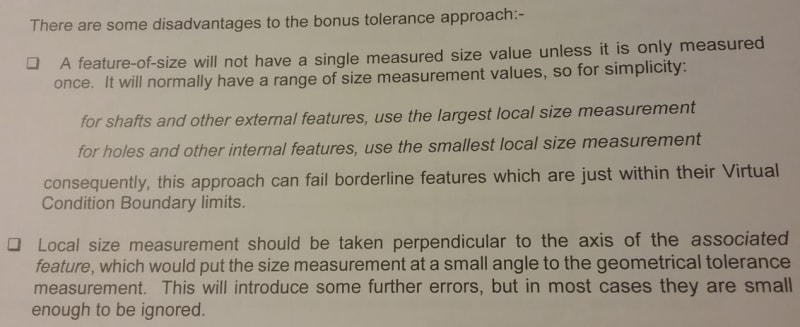
I do have some excerpts from different ISO books and ISO standards. In one of this excerpts it is stated --see below: The local size measurement is relative to the geometrical measurement subject to a small angle. And it is stated that this will introduce some further errors, BUT those errors are small to be ignored.

In the OP's case, I said to myself that the difference is too large (relativelly) for 90.170 to be considered local size, hence I concluded (wrongfully or not) must be UAME size. That was my thought process and even now I do not know if it's fully vetted.

pmarc,
If you are reading this:
1.) Is the axis of the associated feature the axis of the TLSQ cylinder?
2.) Is the TLSQ the default algorithm to determine extracted median line used in the perpendicularity callout in the OP's case? Or do you need to specify which algorithm to be used because nothing is the default? As far as I understood TLSQ is the default only for the actual local sizes, but I am not sure what about determining the EML.


ISO_Bonus_-_Copy_zcxaon.jpg
 
there must be a problem with the engineering it must clearly specify which case UMAE or RMAE
who knows the correct geometrical callout & or foot note on the drawing per ASME or ISO
 
In the OP's case, I said to myself that the difference is too large (relativelly) for 90.170 to be considered local size, hence I concluded (wrongfully or not) must be UAME size. That was my thought process and even now I do not know if it's fully vetted.
Per the OP's latest comments you were correct. 90.170 is the UAME.

there must be a problem with the engineering it must clearly specify which case UMAE or RMAE
This is not necessary. The standard specifies exactly what the conformance requirements are for an MMC perpendicularity specification. Its up to the metrology department to measure it correctly and use the correct envelope/boundary for evaluation.
 
@chez311
apparently they are confused, hell I am confused and every one here trying to scratch their heads.
your the experts, I am just an old engineer, but seem a foot note would have made life simplier
 
Chez311, pmarc,

You seem to be pretty good working with the math standard, so I will ask you: what are those "further errors".
Basically, I am asking what would be the difference in measurement between the size of the hole (smallest local size measurement as specified in the book ) and the size used for geometrical measurement (size of the unrelated actual mating envelope UAME)?

Where is this "small angle" is coming from?

Could you, please reference a sketch in Y14.5.1 (math standard) because I doubt there is one in Y14.5?
I am trying to understand in a little more depth those differences.

I see fig 5-2 (math standard), but I do not think that helps or at least I am not understanding it.

Thanks
 
greenimi,
As you know Actual Local Size is a veritable rats nest. You're asking about the math standard, it should be noted that the current Y14.5.1-1994 makes no mention of Actual Local Size - only the swept spheres interpretation. Only in the unreleased Y14.5.1-20xx draft is there any mention of Actual Local Size.

What book is that from? I guess its an ASME based book, right? If so, the author is clearly referring to the verbiage in Y14.5 since only there does it mention bonus tolerance is related to Actual Local Size, as I noted Y14.5.1-1994 makes no mention of it at all and the calculations for resolved geometry (axis) interpretation therefore do not utilize it - they only use the UAME and RAME size. Even in Y14.5.1-20xx draft the calculations for resolved geometry (axis) interpretation are unchanged from 1994, they do not utilize Actual Local Size - the only one calculation that would have to utilize it would be for MMC straightness, yet no resolved geometry (axis) interpretation is provided in the 20xx (surface interpretation only). Y14.5.1-1994 fig 5-2 is tangentially related to this, it simply shows how the resolved geometry (axis) interpretation can pass a feature while the surface interpretation will fail the same feature due to orientation error.

Additionally, the book suggests Actual Local Size should be taken perpendicular to the "axis of the associated feature" - I'm not exactly sure what they mean by this (UAME axis perhaps?) however any time we talk about an axis it is a perfectly straight ideal theoretical line. From my understanding Actual Local Size should be taken normal to the Actual Size Spine (essentially a tangent continuous DML - this is explicitly state in Y14.5.1-20xx draft and suggested in Y14.5 with figures such as Y14.5-2009 fig 1-1) which is an imperfect feature. Hypothetically I guess there could be some additional errors if we utilized Actual Local Size for bonus tolerance calculation since the largest/smallest Actual Local Size for external/internal features respectively could potentially be different than the UAME size.
 
Chez311,
Chez311 said:
What book is that from? I guess its an ASME based book, right?

No, the book is an ISO book. I am trying to understand how the "no bonus" in ISO works with "bonus" / resolved axis interpretation provided by ASME.
I think even in ISO there is no bonus tolerance and this approach is not documented in any ISO official standards, the concept is widely used across the industry.
I would like to understand, in depth, its usage and implications for the measurements and how this "bonus tolerance" concept is a close approximation of the MMVC requirement.

What means "close"? How close? etc.
For this particular example, for hole -internal feature
Bonus tolerance = measured size- MMS

what is the measured size? How this size is measured in ISO?

Those are my basic questions


how this "bonus tolerance" concept is a close approximation of the MMVC requirement

Assuming the MMVC concept is very similar, if not identical, to ASME surface interpretation/virtual condition requirement:

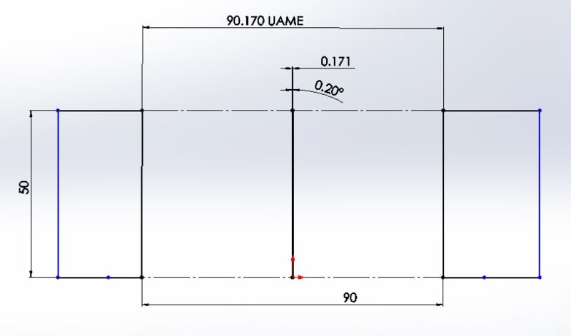
Lets take a similar case to the OP where the UAME = 90.170 and MMVC = 90.000 but instead we now have 0.171 axis orientation error. Since this is greater than the deviation allowed by the bonus tolerance (90.170-90.000 = 0.170) by 0.001 the feature would fail. However, if we measure it according to the surface we can see that your RAME = 90.000 and it does not violate your virtual condition, so it would pass.

Now in this case, and most cases, the difference is minimal (out by 0.001) as the axis is only inclined by 0.2 degrees but as the amount of axis inclination increases the difference between the two increases as well.

I'll have to defer to pmarc on the ISO specific questions.
 
Chez311 said:
However, if we measure it according to the surface we can see that your RAME = 90.000 and it does not violate your virtual condition, so it would pass.

How do you know that? A small sketch would be really helpful.

chez311 said:
Now in this case, and most cases, the difference is minimal (out by 0.001) as the axis is only inclined by 0.2 degrees but as the amount of axis inclination increases the difference between the two increases as well.

That's exactly my question: where you draw the line? at 0.001, maybe at 0.002?
Or inclined by 0.2 degrees ? What about 0.5 degrees?
Why not at 5 degrees?
 
I think the key here umae does not have to be perpendicyular to the datum
rmae doe have to be perpendicular to the datum and that is important.

off the web
The right side of the figure shows that the Related Actual Mating Envelope is the smallest perfect cylinder that is perpendicular to the datum and fits around the physical cylinder. The Related Actual Mating Envelope is always perpendicular to the datum.

The size of the Unrelated Actual Mating Envelope is considered to be the size of the pin.

The axis of the Unrelated Actual Mating Envelope is considered to be the axis of the pin.
Picture
The figure below shows Actual Mating Envelope for an internal Feature of Size.

The center of the figure shows that the Unrelated Actual Envelope is the largest perfect cylinder that will fit inside the physical cylinder without regard to the datum. The Unrelated Actual Mating Envelope will almost never be perfectly perpendicular to the datum.

The right side of the figure shows that the Related Actual Mating Envelope is the largest perfect cylinder that is perpendicular to the datum and fits inside the physical cylinder. The Related Actual Mating Envelope is always perpendicular to the datum.

The size of the Unrelated Actual Mating Envelope is considered to be the size of the hole.

The axis of the Unrelated Actual Mating Envelope is considered to be the axis of the hole.
 
greenimi,

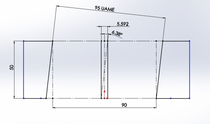
As before, its very difficult to see whats happening so I didn't include the snapshots. Below are two snapshots, the first is what I described in (17 Jul 20 17:36) with UAME = 90.170 and orientation error = 0.001 the second is the exaggerated case with UAME = 95.000 and orientation error = 5.592 so you can see whats going on. As the axis increases in inclination the difference becomes equally exaggerated. Neither of which violates your virtual condition (lets assume the size tolerance would allow the amount of variation shown in both cases).

AXIS_METHOD3_pbjwwt.jpg


AXIS_METHOD4_dhex0v.jpg


where you draw the line?

I would draw it at whatever precision your measurement equipment can reliably measure down to (actually you may have to make a decision including measurement uncertainty too). If a feature violates your virtual condition by 0.0001mm it is nonconforming. I was merely showing the difference between the two interpretations. You asked "how close" and the answer is, for very small angles of inclinations "very close, almost imperceptibly close" and for very large angles "not very close at all".
 
Status
Not open for further replies.

Part and Inventory Search

Sponsor