Continue to Site

Eng-Tips is the largest engineering community on the Internet

Intelligent Work Forums for Engineering Professionals

  • Congratulations SDETERS on being selected by the Eng-Tips community for having the most helpful posts in the forums last week. Way to Go!

Perpendicularity And MMC 2

Status
Not open for further replies.

Alan Lowbands

Aerospace
May 17, 2017
274
Hi,
I was hoping someone might be able to help.

I have just received a report and can't understand how the perpendicularity tolerance was calculated using MMC.
There are two diameter measurements reported, one is stated 'mated' and used for the perpendicularity tolerance at MMC.
The other diameter measurement is different.

Does anyone know which of the two measurements are correct and how the 'mated' measurement is achieved ?
I was wondering if it's software generated but unsure.

I have attached a screen grab.

Any help would be really appreciated

best regards
Alan

 
 https://files.engineering.com/getfile.aspx?folder=33dea6b2-164a-4922-b1d2-14f58912918b&file=Capture10.JPG
Replies continue below

Recommended for you

mfggenggear,

I appreciate your contribution. We all know the theory presented. The question is not about the theory.

It is about the differences/ errors between MMVC and "bonus tolerances" in ISO. Probably a layer deeper than what you are showing (and also what I was showing) in the excerpt from the ISO book.
I am trying to get the nitty-gritty details of those differences and errors.
 
mfgenggear,

I am discussing evaluation of a position tolerance in terms of a feature's axis vs. its surface, not the difference between UAME vs RAME. In ASME we call these resolved geometry (aka axis) interpretation and surface interpretation and for feature with orientation and/or form error they give different results. Surface interpretation takes precedence for MMC/LMC tolerances except for a few specific cases.
 
Alan Lowbands,
Does the drawing show (E) modifier associated with the hole size requirement?

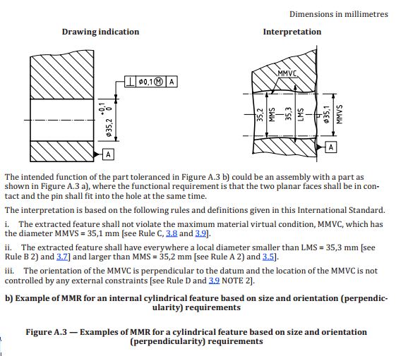
If not, then the verification of UAME size is not needed according to ISO at all, because in ISO for a geometric tolerance specified at MMR/LMR basis (again, without the Envelope Requirement invoked) the only valid interpretation is the surface interpretation.

Snapshot from ISO 2692:2014:
capture2_osywyv.jpg
 
Hi pmarc,

The drawing doesn't show any modifiers.
I think I see what you mean.

regards
Alan
 
pmarc,

Interesting note about the MMR/LMR concept without envelope principle in ISO - I'm not sure if BS-8888 adds any additional requirements to that?

From OP:
The other figure seems to be a software problem that occurs when perpendicularity is measured with MMC.
The ‘mating’ RAME result doesn’t seem to come out correctly and the guy I spoke with doesn’t have an explanation why.

Looks like their QC is going to have to figure out how to properly measure the RAME in order to evaluate it to the surface interpretation.
 
pmarc,

So, when the perpendicularity is called RFS then extracted median line is the one needed to be evaluated, correct? If yes, then the CMM measurement differ greatly when perpendicularity is RFS versus when it is MMB.
(I am bring the CMM in discussion because all this thread was about the CMM report and its measurements results)

On the MMB case, I guess MMVC is qualified by measuring the associated feature such as minimum/smallest circumscribed cylinder (for an external feature) or maximum/biggest inscribed cylinder (for an internal feature) and those two cylinder should be perfectly perpendicular to datum feature B.
If MMVC (calculated value) is bigger than smallest circumscribed cylinder (for an external feature) then the part is qualified for perpendicularity at MMC
If MMVC (calculated value) is smaller than biggest inscribed cylinder (for an internal feature) then the part is qualified for perpendicularity at MMC

Now, if the perpendicularity I called at RFS then the situation change (as probably I described in my newly thread about perpendicularity)
copy-paste
I used 3 sections for simplicity of explanations.

"Let’s say 3 circles / sections are scanned, one circle on the top of the cylinder, one in the middle and one toward the bottom. Those circles are imperfect. From each of those circles a fitted algorithm is used to generate a perfect circle, correct?
(What is by default (if any) the such said algorithm? Total least squares, TLSQ? I am pretty sure the answer is TLSQ)

Then the center of this associated circle is found. Based on the fact 3 sections are measured then consequently we get 3 points/ centers which determine the extracted median line. If this imperfect line. Then, probably the software is trying to fit the smallest cylinder, perfectly perpendicular to datum A, that encompass those 3 center points. If the size of this cylinder is smaller than the TZ (tolerance zone) then the perpendicularity is qualified/ acceptable."


I remember in of your multiple replies on eng-tips you said something along those lines: if one section of the hole/shaft is measured is often good enough, if two sections is luxury and more than two sections is in general unheard of. Sorry I cannot rephrase exactly, but please correct me if I misunderstood you.


Do you agree with my assessment above?

Thank you for my continuous education.


chez311,
Per my knowledge BS8888 follows ISO approach. And yes, their QC definitely needs to catch up.

greenimi,
Instead of answering all your questions, allow me to attach a document that should help you understand the theoretical procedure (perfect verification operator) of establishment of the extracted median line of a cylindrical feature in ISO. It comes from ISO 17450-1:2011. Any deviation from the perfect verification operator adds to the measurement uncertainty. (I hope I will not get banned from this forum one day for sharing this type of info ;-])
 
Perfect. Thank you so much.

So looks like you agree with my assessment about perpendicularity with MMC modifier and its verification by comparison with MMVC.
Then you provided a clear method (confirmation) on how to check perpendicularity RFS.

Now, what I am still unclear is how to judge and think of the uncertainty created when the CMM (for example to keep the original measurement method discussed) is using the "bonus method" / extracted median line method instead of the surface method (for perpendicularity modified at MMC).
Are there any pictures, sketches or even an ISO standard that can explain in more details how to "see" this difference between MMVC and its close approximation offered by the "bonus tolerance" ?
How to transition from TZ approach (and EML) to MMVC?

I do not have much ISO material and ISO books and in the ones I have there is no such of picture(s) or explanation.


greenimi,

Sorry, but I am not aware of any ISO standard that could explain in greater detail the difference between the MMVC approach and the extracted median line interpretation utilizing the concept of bonus tolerance.

As for "pictures, sketches"... in my opinion chez311's illustrations give a nice flavour of the difference (with the assumption of the EML being perfectly straight).
 
pmarc and all,

Thank you for your input.

Based on your metrology experience, do you know why the CMM is not checking/ qualifying the features (internal or external features) based on MMVC approach?
(I am thinking this because in ASME, surface interpretation take precedence anyway and in ISO GPS there is ONLY surface interpretation when a feature is modified at MMC)

Is it because the outer tangential algorithm (smallest circumscribed cylinder or biggest inscribed cylinder) is very sensitive to outliers?
Is it because it can be confused with RAME (which is used to establish a datum axis of a Secondary or Tertiary datum)?


greenimi,

Those plots are just using trigonometry to calculate the RAME size for a given size tolerance (12 +/-0.2) and a given orientation/position tolerance (0.3) if the feature has the maximum possible orientation error according to the axis interpretation (ie: bonus tolerance). One curve is if the feature is at MMC size (form error is not considered so UAME = MMC size) so maximum orientation error is the tolerance given in the FCF and the other curve is if the feature is at LMC size (UAME = LMC size) so the maximum orientation error is the tolerance + MMC - LMC.

Since we are interested in the discrepancy between the axis and surface interpretation (ie: why measured RAME size at maximum axis orientation error is different than the calculated virtual condition) this discrepancy for orientation hinges on increased angular deviation. Thus the x-axis is the feature height, as this is a trigonometric relationship and for a given tolerance zone width the height of the feature (the height is not given in the tec-ease example referenced in that thread) is the only variable besides size (which is already used to produced two difference curves for a given size tolerance) which we can change to impact the maximum possible angular variation ie: angular deviation = arctan(p/t)* where p is the tolerance zone width given in the FCF and t is the feature height.

*Or in the case of the feature at LMC the angular deviation is arctan((MMC-LMC+p)/t)
 
chez311,

Did you use CAD to get the values you posted or you have a mathematical formula?
chez311 said:
Its worth noting that the measurements you made in CAD for the RAME are the same as would be made under the surface interpretation and actually show the disconnect between the two interpretations. For example in your (8 Jun 20 09:28) post the feature passes per the axis interpretation (axis falls within 0.3 tolerance zone) but fails the surface interpretation (RAME of 12.505 greater than VC of 12.5). Therefore the feature is nonconforming.

I am trying to get youre numbers with no CAD availability (for now)

 
greenimi,

Sorry I wasn't ignoring you I wanted to do some additional verification before I posted the formulas. I'll probably be creating another thread as I've noticed a few interesting things, but a lot of stuff came up - I meant to provide these sooner. I got the notification you posted the question in the other thread and it reminded me I never responded.

These equations are:

p = tolerance zone width as specified in the FCF
t = tolerance zone height
D_MMC = MMC size
D_LMC = LMC size

For an External Feature(plots on referenced thread):
MMC_RAME = D_MMC/cos(theta) + p
where theta = arctan(p/t)

LMC_RAME = D_LMC/cos(theta) + (D_MMC - D_LMC + p)
where theta = arctan((D_MMC - D_LMC + p)/t)

For an Internal Feature just subtract the second term.

Note theres no magic here - these can all be derived with trig from my above figures (the LMC case equation just accounts for the fact that the allowed tolerance p increases for the axis interpretation due to bonus tolerance by an amount of D_MMC - D_LMC). I see you asked about the figures in the other thread ( - these are the same as the ones I show here just with different values. It can essentially be created with less than 10 lines, I can post a solidworks (or even a .dwg - though I'm not sure if the construction lines will come through properly) file but I would think the multiple pictures provided here should give a reasonable guideline.
 
chez311 said:
greenimi,

Sorry I wasn't ignoring you I wanted to do some additional verification before I posted the formulas. I'll probably be creating another thread as I've noticed a few interesting things, but a lot of stuff came up - I meant to provide these sooner. I got the notification you posted the question in the other thread and it reminded me I never responded.

These equations are:

p = tolerance zone width as specified in the FCF
t = tolerance zone height
D_MMC = MMC size
D_LMC = LMC size

For an External Feature(plots on referenced thread):
MMC_RAME = D_MMC/cos(theta) + p
where theta = arctan(p/t)

LMC_RAME = D_LMC/cos(theta) + (D_MMC - D_LMC + p)
where theta = arctan((D_MMC - D_LMC + p)/t)

For an Internal Feature just subtract the second term.

Note theres no magic here - these can all be derived with trig from my above figures (the LMC case equation just accounts for the fact that the allowed tolerance p increases for the axis interpretation due to bonus tolerance by an amount of D_MMC - D_LMC). I see you asked about the figures in the other thread ( - these are the same as the ones I show here just with different values. It can essentially be created with less than 10 lines, I can post a solidworks (or even a .dwg - though I'm not sure if the construction lines will come through properly) file but I would think the multiple pictures provided here should give a reasonable guideline.

Thank you chez311,
Let me make it in my CAD and understand it. Thanks again
 
Status
Not open for further replies.

Part and Inventory Search

Sponsor