Continue to Site

Eng-Tips is the largest engineering community on the Internet

Intelligent Work Forums for Engineering Professionals

  • Congratulations cowski on being selected by the Eng-Tips community for having the most helpful posts in the forums last week. Way to Go!

Perpendicularity callout with curved datum 1

bc23

Mechanical
Mar 7, 2025
21
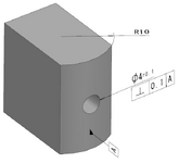
I re-created this drawing for illustration purposes. All the flat sides/surfaces are actually not flat (so cannot be used as datums).
The intention is for dia4 hole to be perpendicular to curved surface (R10). But is this FCF correct? (whether by ASME or ISO)
If Datum A was re-defined as a specific line on this curved surface, would it be legal? (But it would be difficult to measure also)
1744001411806.png
 
Replies continue below

Recommended for you

well I gave an incomplete advice because i had incomplete information. where is the datum mating surfaces.
i thought of true position but did not give advice because datums are important. so I will add an educated guess.
per OP post face are angular. while datum targets work irregular surfaces can cause rocking.
In my opinion datum gage point would be better. so in this case we need 3 datums. use gage points at mid center of each
3 datums. but I have met the minimum requirement of points of location . however to be more precise for the inspect fixture
use tooling balls or tooling holes in each datum location. then use stack up distance from datum point(gage point)
to obtain center line of the hole. then true position can be obtained. that's how a taper is measured.
sorry if I don't quote from direct ASME rules as I don't have the spec. and don't justify purchasing it sense I am retired.

with a stack up dimension the hole dimension can be established. as well as the center of the radius. and locating on the gage points
 
bc23,
Note that my suggestion was more about addressing the datum target setup itself based on the information provided in the initial post. Keeping perpendicularity tolerance for the hole does not guarantee its location close (that is, within a tolerance) to the tangency point. To guarantee that, a position callout relative to A, B and C should be specified.

If the curved surface interacts with a similarly-shaped surface in the mating part, then I wouldn't probably even consider the option with the tangent datum target plane A1.
Although your advice was directed to the original post, I extrapolated it as: Define appropriate datum A for the hole perpendicularity condition. Add datum B, C to fully constrain that part & support Dtm A. This Dtm A could be a datum target as suggested, but can also be another surface from which I would constrain R10.
This would specify hole Position FCF w/ A|B|C, and R10 Profile of Surface FCF w/ A|B|C. (a bit similar to Burunduk's suggestion)
 
Last edited:
If the point of making a tangential datum A and orienting the part with other datum features, then skip the tangential datum and use angularity or parallelism to whatever alternate features are supposed to be used.

To put it another way, if the other features are ones that could be used in a drill press to hold the part still, a tangential feature would simply block access by the drill and is not required.
 
Define the plane tangent to the arc at its quadrant as datum target plane A1.

Next, define datum targets B and C on some other features of the part to fully and repeatably immobilize the part for the check of the perpedicularity tolerance.

Then, specify the following, or similar, note (taken from para. 7.24.10 in Y14.5-2018 or para. 4.24.14 in Y14.5-2009):
WHERE ONLY DATUM FEATURE A IS REFERENCED, DATUM FEATURES B AND C ARE INVOKED ONLY TO RELATE THE TARGETS THAT ESTABLISH DATUM A.

Finally, add the missing diameter symbol in front of the perpendicularity tolerance value and keep A as the only datum reference in that callout.

Pmarc,
For the sake of discussion and learning purpose, let me ask you this question:
What wold be the geometrical difference between your solution (above) and a profile with tangent plane modifier to A( datum feature "A" being the Ø4mm hole)
I am thinking something similar to fig 12-15 (2018).

Well, none of us know the OP's trully functional requirements, hence I am tossing out my question there to learn more from your experience and knowledge.
 
Last edited:

Part and Inventory Search

Sponsor