Continue to Site

Eng-Tips is the largest engineering community on the Internet

Intelligent Work Forums for Engineering Professionals

  • Congratulations waross on being selected by the Eng-Tips community for having the most helpful posts in the forums last week. Way to Go!

Pinned vs Fixed Connections in Practise 3

Status
Not open for further replies.

structuree

Structural
Feb 20, 2022
10
I'm trying to get my head around how pinned vs fixed connections appear in practise. I'm struggling to identify whether a connection will result in an induced moment. It doesn't always seem as straightforward in practise as it does in theory.

For example, I am aware that typically a connection with 2 x bolts would be designed as pinned, and you wouldn't consider it as taking any moment, but you add 4 or 6 bolts, and you're probably trying to crank moment into the connection. Where is the line drawn?
 
Replies continue below

Recommended for you

I generally treat connections as pinned unless I'm specifically designing for a moment capacity. I also briefly consider what effects, if any, a moment applied at the connection would have. Two bolts or four, it doesn't matter (for safety during construction, you often need four fasteners). Just the axial load, unless you have a large moment will impart a degree of fixity.

Rather than think climate change and the corona virus as science, think of it as the wrath of God. Feel any better?

-Dik
 
So will the bolted connections have some moment fixity? Yes. Do we care about it? Not really if you're designing as a pinned connection and you're not relying on the moment capacity of the connection. You can just ignore it and go about your day. Unless like Dik said, you are specifically designing and depending on the connection to take moment.
 
In the US, connection are classified as Simple Shear Connections, Partially Restrained Moment Connections, and Fully Restrained Moment Connections. I bet the idea is similar in the rest of the world, but the category names are probably different.

Simple shear connections inevitably have rotational stiffness, so there will be a beam end moment. However, if the connection is proportioned and detailed correctly, the moment will be low, so the connection can be idealized as hinged in the design calculations. In the AISC Manual Parts 9 and 10, there are checks and detailing requirements to ensure the connection is sufficiently flexible. For example, for a single plate connection, the plate must be thin enough so that it would yield or have bolt "plowing" into the edges of the holes before failure of any of the brittle limit states. There is something like a ductile fuse in other words. As another example, for a double-angle connection welded to the support, there is no weld along the top of the angle so that it can flex away from the support, thus providing flexibility.

On the other end of the spectrum, fully-restrained moment connections inevitably have some rotational flexibility, so the end of the beam can rotate relative to the supporting column. The rotation should be small enough so that the connection can be idealized as rigid.
 
EcoGen said:
So will the bolted connections have some moment fixity? Yes. Do we care about it? Not really if you're designing as a pinned connection and you're not relying on the moment capacity of the connection. You can just ignore it and go about your day. Unless like Dik said, you are specifically designing and depending on the connection to take moment.

Can you think of an example where fixity in one member increases stress in another?

BA
 
I think it also needs to be mentioned that implicit in the answers above (not including BAretired) is the assumption that by consider the treatment of the connection as a pinned connection it is a conservative approach. This is often the case but not always. It is still incumbent on an engineer to recognise where this assumption doesn't hold.

Furthermore even in a 4 bolt connection once you consider hole tolerances plus hole yielding you end up fairly significant end rotation. This is readily calculable but there has also been significant research on this.

dik said:
Two bolts or four, it doesn't matter (for safety during construction, you often need four fasteners)
Could you care to elaborate? Or is this a clip angle thing. Because for a cleat I see no issue with 2 bolts.
 
The only true pin, is an actual single pin. Everything other than a single pin/bolt has some fixity. But as engineers we tell ourselves the lie that its pinned, because its a simple approach.

Take the example below, that’s designed as a pinned connection from one beam to another. By designing your beam as pinned, you’ve given it enough midspan stiffness that it doesn’t ‘need’ to transfer moment at its end. Overload the beam and that will be its first line of defence, the midspan will yield and then it will try to claim some end fixity. If the supporting member can’t accommodate this end moment then you’re into collapse. Also, the plate shown below is less than 12mm classifying it as ‘flexible’ in the code (here, at least).

My view is - take a simply supported beam that carries a constant load and has done for years. Say i come along one day and weld haunches to the end of it. Does that mean its all of a sudden going to collapse? No. The beam doesn’t even know they’ve been added because it doesn’t need to use them.


A09D8B95-0524-4141-AEE2-0D447D3C713A_qwgh2n.png
 
MIStructE_IRE said:
My view is - take a simply supported beam that carries a constant load and has done for years. Say i come along one day and weld haunches to the end of it. Does that mean its all of a sudden going to collapse? No. The beam doesn’t even know they’ve been added because it doesn’t need to use them.
No the beam isn't going to suddenly collapse but what of the supports? Some supports are not BUILT to take the moment. If changes in the loading conditions (wind, live load) come along then you you push the supports beyond strength or serviceability criteria.

rowingengineer said:
I am from the semi rigid group, if it takes moment design it as such.
Agreed. It isn't like we lake sufficient tools to do so. At the very least a designer should be aware when the simplifying assumptions are not being conservative. And assuming a pinned connection isn't always a conservative assumption like is sometimes suggested.
 

I was referring to columns where it is common to have 4 fasteners for safety reasons. The Canadian S16 recommends that there be 4 unless special precautions are implimented. I think the AISC is similar and predated S16. It's usually at the base of columns that fixity is a concern.

Rather than think climate change and the corona virus as science, think of it as the wrath of God. Feel any better?

-Dik
 
Everything other than a single pin/bolt has some fixity. But as engineers we tell ourselves the lie that its pinned, because its a simple approach.

I think I'm generally aware of connection fixity just to make sure there are no unintended consequences. Also from 50 years back regarding plastic design. There's a fundamental lemma by Feldberg that states that, barring instability issues, if you strengthen any part of an structure, the resulting structural system will not be diminished in strength. It might not be improved, but it will not be weakened... it's a pretty obvious concept, but nice to know.


Rather than think climate change and the corona virus as science, think of it as the wrath of God. Feel any better?

-Dik
 
dik said:
I was referring to columns where it is common to have 4 fasteners for safety reasons.
Ah yes. That makes sense.

dik said:
There's a fundamental lemma by Feldberg that states that, barring instability issues, if you strengthen any part of an structure.
I'm unaware of that lemma. Strengthen makes sense. STIFFEN does not. And that is what we are talking about here with a pinned/semirigid/rigid connection.

Stiffening can reduce the ultimate capacity of structures.
 
It makes sense with any type of structure... even 'glued'... About 50 years back I came across the lemma as a result of a comnment in Massonette and Save's (sp? and one of the best plastic design texts ever printed) plastic design text and located it at the time... I tried to find it about a decade back without success...

Rather than think climate change and the corona virus as science, think of it as the wrath of God. Feel any better?

-Dik
 
Making joints more rigid is not always a good idea. Column BD in the structure shown below takes nearly 30% more load if Joint A is changed from pinned to fixed.

Capture_lzqwhu.png

BA


My points,

- If the question is for the column bases with 4-6 anchor bolts , still the base could be assumed pinned depending on the footing rotational fixity.

- If the connection is for continuous beam or frame , ( say single span portal frame ) if the beam column connection is rigid , still the connection could be assumed flexible for the beam if the stiffness of the beam 10 times of the stiffness of column..However, the same connection could be assumed as fixed for the column ..

- The semi-rigid steel connection design in some cases could be more economical .

I will suggest you to look ;
-Section 6.4 Base Stiffness SCI P397 the following doc.
-Design of semi con. braced frames SCI P183 the following doc.
-Structural modelling of the conn. 4 STRUCTURAL MODELLING ..
 
 https://files.engineering.com/getfile.aspx?folder=567820ab-74ae-4767-870d-e53ca39afddb&file=SCI_P397-Elastic_design_of_single_bay__steel_EC_3_nominally_pinned_bases__secure_(1).pdf
BAreitred said:
Making joints more rigid is not always a good idea. Column BD in the structure shown below takes nearly 30% more load than when Joint A is changed from pinned to fixed.
Good post. A nice simple example.

Like you say rigidity is not always a good idea. There is a reason why structural bearings exist and that significant amounts of money is spent ensuring supports DO behave as pins or as rollers or as both.

HTURKAK said:
My points,

- If the question is for the column bases with 4-6 anchor bolts , still the base could be assumed pinned depending on the footing rotational fixity.
Most of the time you don't want your footing itself providing rotational moment. In many cases where you have a column on a braced frame there is so little end rotation it doesn't matter if it is fixed or rigid. I gave this example to a junior employee this week. In the frame analysis program a simple change from pinned to rigid connection meant the connection only saw a negligible amount of moment, up from zero. So in this case detailing of the HSS base to be flexible wasn't vital.

For a portal frame this would not be the case. I'd be uncomfortable designing a base connection something too rigid, because footing rotation and subsequent concrete cracking is a realistic scenario under deflection. I've seen results of the end wall of a portal rotating inwards because the only wind restrain was the purlins which buckled. The building survived just 'fine' but significant foundation rotation occurred and the cracking around the footings was quite visible.

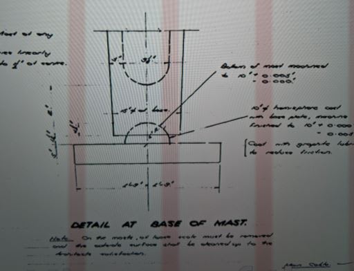
Othertimes you absolutely want column rotation and provide a bearing for it. (I've posted this before, but it is a great and certainly not modern example.)
08357-p0001-000007-004-003-w_1_foc9qt_k5qvfc.jpg
C01_b0qmpp_j2vwvx.jpg
 
dik said:
There's a fundamental lemma by Feldberg that states that, barring instability issues, if you strengthen any part of an structure, the resulting structural system will not be diminished in strength.

I believe this lemma is true. I would like to have a reference, but couldn't find one quickly. Do you have one that you can share?
 

No I don't. I had a copy about 50 years back that I located, so I know it existed. I don't know if it's been withdrawn and/or modified. The comment was originally made in Maissonette and Save's text and I looked it up at the time and found it. I tried to locate it again about a decade back without success.

Rather than think climate change and the corona virus as science, think of it as the wrath of God. Feel any better?

-Dik
 
Status
Not open for further replies.

Part and Inventory Search

Sponsor