Continue to Site

Eng-Tips is the largest engineering community on the Internet

Intelligent Work Forums for Engineering Professionals

  • Congratulations pierreick on being selected by the Eng-Tips community for having the most helpful posts in the forums last week. Way to Go!

Plate design with max deflection below 5 microns

Status
Not open for further replies.

Anurag K

Mechanical
Mar 27, 2023
11
Hey everyone,

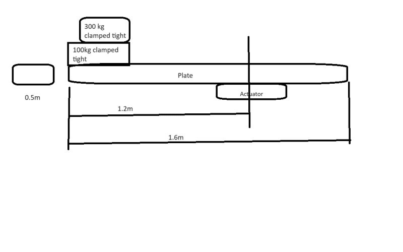
I have a project that I am working where I am designing a plate mounted/fixed to a heavy duty rotary actuator; the actuator is fixed. A 100kg blocked is clamped to it and upon it a 300kg weight is clamped. The whole plate length is 1.6m long with the actuator sitting 0.4m from one end.

My objective as given by my supervisor is to design a plate which when loaded has max deflection of 5 microns.
I modeled it as a cantilever beam and did some hand calculations and the thickness came out to be 350mm which was an immediate no. The plate thickness has to be within 100mm

How do I model this in SolidWorks CAE, what boundary conditions do I give it? I was suggested by my senior engineer that when two parts are clamped tight, it adds some stiffness. How do I factor all that in? I have attached a picture for reference.

TL;DR - How to model the Plate in the below picture accurately in SolidWorks CAE in the way it is mounted and clamped. Please suggest.

Material of Plate is A36 HRS

I really appreciate you all for taking time to read this length post.

turret_pjdn3d.png
 
Replies continue below

Recommended for you

Loaded by what? Gravity?

Just model the parts as one solid mass. You will need dimensions for the block and weight.
 
I assumed that when the block and weight get clamped to that plate, the plate will be under stress. That the plate will deflect at the left end like a cantilever beam.
 
Stiffening the tip of a cantilever beam is a very small benefit 'as any fule kno', thank you Molesworth. So, switching to SW won't help either, this is dead easy to analyse by hand, basically first year strength of materials or equivalent. So if you let us know the dimensions of the 100 and 300 kg masses, and their materials, we can confirm or not your hand calculation.

Cheers

Greg Locock


New here? Try reading these, they might help FAQ731-376
 
Lets take their material and width as same as the plate, and their heights as 100mm
 
Given the requirements and the description I assume this is a dynamic problem. What is the load and how are you analyzing this? I am not familiar with Solidworks CAE.
 
So in the case you analysed is the cantilever free to deflect or is it supported at the actuator? Where is this 5 micron deflection measured?


Cheers

Greg Locock


New here? Try reading these, they might help FAQ731-376
 
SolidWorks Simulation has remote mass and distributed mass features so you don't have to model the blocks - you can just apply their mass to a selected surface of the plate. Then you'll need to add a gravity load.

Fixed constraint is just an assumption and may introduce spurious stress concentrations so the most accurate way would be to model the connection with the actuator but ignoring it should be fine too.
 
@ThomasH
There are no loads per se, there are masses clamped to the plate. And how exactly these masses that are clamped to the plate should modeled as is what I am trying to figure out.

@GregLocock
The plate is free to deflect at both ends but the max deflection should be 5microns (anywhere in the plate) and yes, it is supported at the actuator.


"There are no loads per se, there are masses clamped to the plate."

So this thing floats freely in outer space? Or does gravity act on the parts? Do you need to account for the accelerations imparted by the actuator?
 
"There are no loads per se" ... then there are no deflections !

There is at least weight (or possibly loads from the launch if it is in space), but most likely the actuator is doing more than just sitting there "fat, dumb, and happy" and (I suspect) actuating ...

"Hoffen wir mal, dass alles gut geht !"
General Paulus, Nov 1942, outside Stalingrad after the launch of Operation Uranus.
 
@btrueblood and @rb197
There is gravity on the parts.

A 100kg block is clamped tight to the plate and a 300kg block is clamped tight to the 100 kg block.
The plate is mounted onto the actuator which is fixed. Gravity acts.
How does one accurately model it in FEA?
 
yeah, that's what we meant by "self weight".

But this is a hand calc ... you have a cantilever with a load of 400kg (= 4000 N) at a distance of about 1m, so you can calc (or use standard formulas) to get the tip deflection in terms of I ... I = bd^3/12, b = 0.5m, d = thickness, TBD; deflection < 5E-6 m ... QED.

Should this be in the student forum ?

"Hoffen wir mal, dass alles gut geht !"
General Paulus, Nov 1942, outside Stalingrad after the launch of Operation Uranus.
 
I just realised you haven't really drawn how it works. Is the beam supported on a pin joint on the far right, or is it encastre (built in).

Or is the whole thing dangling off the actuator?

To be honest without a much better drawing I don't think I'm going to bother with this.

The reason you aren't getting much help with the SW side of things, I suspect, is that not many FEAers use SW, and you seem to be asking for stuff that should be obvious from tutorials or youtube.

Cheers

Greg Locock


New here? Try reading these, they might help FAQ731-376
 
my apologies, reread your OP and noticed "the actuator is fixed" and "did some hand calculations and the thickness came out to be 350mm". Share your hand calc ...

I'll give it a try ...
4000N load, 1000mm arm, 500mm width, 100mm thick, steel (E = 210,000 MPa) ... I = 500*100^3/12 = 4.17 E7mm4
cantilever deflection due to t tip point load ... PL^3/(3EI) = (4000*1000^3)/(3*2.1E5*4.17E7) = 4E12/2.6E13 = 0.15mm > 0.005mm
I get thk = 310mm (like you did) ... I = 1.24 E9, deflection = 4000*1000^3/(3*2.1E5*1.24E9) = 4E12/7.8E14 = 4/780 = 0.005 mm
I am approximating to a cantilever with a tip load. I could extend the deflection calc by including the remaining portion of the beam (200mm) continues the deflecting as the slope at the end of the 1000mm length cantilever I used. Another choice (which'll produce the same result) would be a cantilever L = 1200mm with a point load at a = 1000mm ... d = (4000*1000^2*(3*1200-1000))/(6EI) = 2.6/2 * 0.15 = 0.195mm ... so thicker than 310mm required (like your 350mm). I'm not suggesting that this is a good design, but a solution of the problem as presented, and confirming that the goal (thk < 100 mm) is unachievable for the deflection limit required.

Now I'm wondering if the overhand is part of the solution, but I don't see it ...

"I was suggested by my senior engineer that when two parts are clamped tight, it adds some stiffness." yes, it does, but not enough to affect the results, and you haven't given us the data ... the width of these clamped blocks. What the clamping does is to enforce a linearity on the slope of the cantilever over the span of the clamped items (as the beam is effectively much thicker).

"Hoffen wir mal, dass alles gut geht !"
General Paulus, Nov 1942, outside Stalingrad after the launch of Operation Uranus.
 
Anurag K said:
There are no loads per se, there are masses clamped to the plate. And how exactly these masses that are clamped to the plate should modeled as is what I am trying to figure out.

If there is no loads there will be no deformation. But if you are using gravity (mass) and deflection, is the purpose of this to get a specific stiffness? Could this be a work-around for stiffness instead of using the natural frequency? The parameters you are using are the same and 5 micron seems from a static point of view, pointless.

Perhaps your question is more related to how to use SW for this, in that case I have nothing to add right now.
 
This problem seems to involve basic mechanics of materials - how to minimize mass while maximizing bending stiffness and strength - and does probably not require any finite element analysis whatsoever. Your superior should be able to explain why a solid plate concept is a waste of materials and why solidworks is not needed to investigate this concept.

Here are some hints: use a thin plate (as in e.g., 10 or 20 mm thick, not 350 mm, which is what one would expect to see in a nuclear reactor pressure vessel) and add stiffeners. Alternatively, place I-beams side-by-side and connect top flanges with thin plate strips perpendicular to the cantilever direction.
 
Also ask whoever set the 5 micron limit how they propose to measure it. A spec you can't measure is just an arbitrary make-work.

My guess in the absence of any useful information is that the static stiffness of this thing will be massively affected by the actuator.

Cheers

Greg Locock


New here? Try reading these, they might help FAQ731-376
 
I wonder if the problem was posed as "I want the thickness to be less than 100mm." "Ok, what deflection (to size the thickness) ?" "Oh, I don't know, something small, 5 microns."

So the answer would be "with 100mm thick, I get a deflection < 0.2 mm" (and that's hard enough to measure).

"Hoffen wir mal, dass alles gut geht !"
General Paulus, Nov 1942, outside Stalingrad after the launch of Operation Uranus.
 
The above design is part of a precision level CNC grinding machine to grind parts that are going to be used in an engine.
Therefore the max deflection is set at 5 microns; as the max deflection increases the parts won't be accurate to their design.

I want to check every avenue before I take my design results to my supervisor.
 
Status
Not open for further replies.

Part and Inventory Search

Sponsor