Continue to Site

Eng-Tips is the largest engineering community on the Internet

Intelligent Work Forums for Engineering Professionals

  • Congratulations KootK on being selected by the Eng-Tips community for having the most helpful posts in the forums last week. Way to Go!

Plate Shear Stress

Status
Not open for further replies.

406Eng

Structural
Jun 27, 2019
9
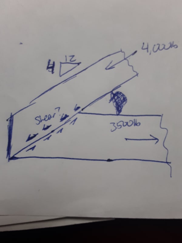
Alright I am hoping someone can help me with some basic mechanics of materials, maybe I am just overthinking this but I can not decide the proper way to tabulate the shear stress. The attached image shows two members which will be fastened with a plate (much like the heel joint of a truss or rafter) I am trying to determine the shear forces that would act on such a plate. You have a member in compression at an angle and a member in tension along the horizontal plane. My question is this, how do you determine the "shear stress" the plate would experience acting along the joint between the two members? My thought is either you consider each force individually assuming that the plate is cantilevered from the other member or is it additive where you assume the plate experiences shear from both members simultaneously?
 
 https://files.engineering.com/getfile.aspx?folder=e5d235e1-0bb4-41bc-a15f-3e1ad0cdd4e4&file=20200318_073801.jpg
Replies continue below

Recommended for you

I'm not seeing your plate in the sketch. What kind of members are they? How/where are they supported?
 
As phamENG stated, we need to know how this is supported. As it is sketched, the node is not in equilibrium, and the members will simply move and rotate. How it is supported will determine which force is being transferred to which member and which force is being transferred directly into the (non existent) support.
20200318_073801_u69plm.jpg
 
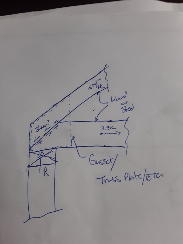
My apologies, I have attached a better sketch. To answer your questions, the support is at the end of the horizontal member. This was a general question in regards to the mechanics of it which is why I did not provide a material (I have seen this scenario with both wood and steel) but if it helps lets assume that they are dimensional (2x4) lumber.
 
 https://files.engineering.com/getfile.aspx?folder=3ca6e15e-49a6-4784-8cd4-7b5ccec0f111&file=20200318_082008.jpg
Just look at the forces acting on one side of the joint and determine the resultant in the direction you are looking for. The easiest way to get this is just to look at the top chord as it is already in the correct direction and is the only force. The shear in the joint is 4k.

Also, you can embed pictures in the post by using the image button - this helps everyone reviewing the post by removing the need to download a separate file.
image_button_z8ftgb.jpg


20200318_082008_trhziq.jpg
 
Note that the joint is not in equilibrium. Do a check on the tension chord member, T (3.5k) = C*cos θ, in which C = compression chord force = 4k. Once the equilibrium is reached, assume the compression force is correct, then the shear force in the joint is as pointed out by dauwerda.
 
New Structural Guy - based on the way you expanded your explanation, I'm guessing those numbers were made up to facilitate discussion. For future reference - if you post something on this forum, make sure even your hypothetical statements are as correct as you can make them. No matter what the question is, if there is an arthritic arithmetic error or some other little thing, it will completely derail the discussion for a considerable period of time. I've learned that the hard way. Granted, it's not exactly a bad thing - you're here asking for help so if you display an apparent lack of knowledge, everyone wants to help you learn. Just something to remember.
 
Another hint, check the angle between the chords, θ = cos[sup]-1[/sup](3.5/4), see what you got. Does it agrees with your original sketch with 4(V):12(H) slope?
 
And, if you mean arithmetic error, you should be sure to say that too, because picking on arthritic people is not nice. 😊 The point is that you should be thinking and conversing like a real engineer, not like some dumb…?. There is nothing wrong with approximations and assumptions, as long as we know that’s what they are. Our’s is a fairly precise profession in terms of numbers, terminology, etc. Think a few minutes, and provide all the needed engineering info for a meaningful discussion, such as reaction location and direction. Those are important to your problem/question. Remember, we can’t see what you are looking at from here. Otherwise, we wonder, if he doesn’t do that part right, what else about his assumptions and descriptions is all messed up.

Edit: Not the normal assumption for that sketch, but, if the joint was hung from above, then you would have 3.5k going across that weld or gusset, not 4k. And, that was your exact question. Another way of thinking of it is, which member force are you trying to drag across that joint?
 
dauwerda - Thanks for the clarification and sorry for the confusion ...retired13 is right that I was just trying to demonstrate the idea but I will be sure going forward to provide actual numbers and present a more to-scale and logical case.
 
Doh! Nothing like putting my foot in my mouth while telling somebody not to put their foot in their mouth. Thank you for proving my point, dhengr!
 
Status
Not open for further replies.

Part and Inventory Search

Sponsor