Continue to Site

Eng-Tips is the largest engineering community on the Internet

Intelligent Work Forums for Engineering Professionals

  • Congratulations KootK on being selected by the Eng-Tips community for having the most helpful posts in the forums last week. Way to Go!

Position Control on Circular Face

tlwhite0311

Mechanical
Jan 4, 2018
7
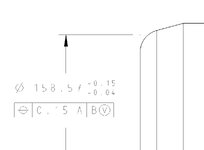
I came across this tolerancing scheme that struck me as odd. There is a position tolerance on a circular face where a conical feature has been faced off (dare I say a spot face?). I thought that you cannot control anything that is not a feature of size (i.e. with two opposing points anywhere along the feature) with Position. I spoke to an inspector and he sounded a bit confused when I mentioned opposing points, he said he could find the position of the face by generating lines on the CMM from the face of the cone and then those lines would generate points where they intersected the face, he could then use those to find the position of the face. I have never used a CMM yet so I don't know anything about that, but I wanted to get another opinion. See image for reference, the left is the top view, the right is the front view.

questionable_gdt.jpg
 
Replies continue below

Recommended for you

One of the definitions in ASME Y14.5 for a feature of size is a "circular element". Arguably it is one and the position callout can be considered valid.
I agree with your discomfort with this though. It's not clear how an Unrelated Actual Mating Envelope, that is needed to derive the controlled axis, should behave like for this nominally 2D circular intersection edge (in reality it may not be truly 2D and it will also end up slightly chamfered for a machined part). Also should it be an axis in the first place or perhaps a center point for the circular element? There seem not to be enough information in the standard for such cases.
 
The is a case the committee for ASME Y14.5 has ducked/dodged for decades. Similar to using a position tolerance on a countersink.

The CMM guys can always make some analytical argument, but they cannot make a fixture or mating part that contacts neither the conical face or the flat face and still locates on the controlled diameter.

Using circular runout on the cone is more representative of the interaction one can expect between the cone and whatever the mating feature is.
 
One of the definitions in ASME Y14.5 for a feature of size is a "circular element". Arguably it is one and the position callout can be considered valid.
I agree with your discomfort with this though. It's not clear how an Unrelated Actual Mating Envelope, that is needed to derive the controlled axis, should behave like for this nominally 2D circular intersection edge (in reality it may not be truly 2D and it will also end up slightly chamfered for a machined part). Also should it be an axis in the first place or perhaps a center point for the circular element? There seem not to be enough information in the standard for such cases.
I had the same thoughts about the "circular" element clause. Position is supposed to technically control an axis but a 2D circular element has a point. Perhaps it doesn't say it NEEDS to be an axis in the standard. I will have to go and look. Thank you for your reply.
 
How is the pos tol measured to the thread?
Datum feature B is referenced at MMB, so ideally datum axis B should be simulated by a threaded hole of a corresponding pitch diameter, that is also constrained to be perpendicular to the simulator of datum A (a planar face).
 
Datum feature B is referenced at MMB, so ideally datum axis B should be simulated by a threaded hole of a corresponding pitch diameter, that is also constrained to be perpendicular to the simulator of datum A (a planar face).
Don't they measure internal threads with a joe plug? A device that can simulate the pitch diameter. What is the equivalent for external threads?
 
Don't they measure internal threads with a joe plug? A device that can simulate the pitch diameter. What is the equivalent for external threads?
Since this one is referenced at MMB it is supposed to be of a fixed size and allowing some datum shift.
 
Since this one is referenced at MMB it is supposed to be of a fixed size and allowing some datum shift.
So what would you use then? Can you like precision grind an internally threaded hole to the MMC size of the threads?
 
Theoretically I would need to make it at the virtual condition for perpendicularity to datum A.
 
Theoretically I would need to make it at the virtual condition for perpendicularity to datum A.
Sorry maybe I wasn't being clear. What actual tool in the inspection room would be used to simulate those those external threads when inspecting this part?
 
Sorry maybe I wasn't being clear. What actual tool in the inspection room would be used to simulate those those external threads when inspecting this part?
A gage with a planar face to simulate the primary datum plane A and a threaded hole perpendicular to it, with a pitch diameter of the MMC size of the external thread's pitch diameter plus the .002 perpendicularity value.

Is such a gage difficult to produce? Of course. Does that make little sense functionally as it does not seem to be corresponding to possible assembly conditions with a mating part? Sure. That's among the other things that should be pointed out to the drawing originator. I don't think that external thread should be a secondary datum feature. I am also from the camp that says don't use any material condition or boundary modifiers on threads.
 
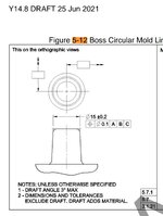
At least they dimensioned a physical edge. At my previous company where we designed molding rings the foreign drafters usually made drawings like these:
(it is made up now, but you get the picture) Tolerance and position on a theoretical intersection.
Annotation 2024-12-03 102531.jpg
 
Whuzhee,
I think what you are showing is actually standardized in Y14.8... because of draft angles. Dimensions apply to mold lines.
The definition for the relevant Actual Mating Envelope is also modified from Y14.5 to make sense of it. Don't remember the exact details right now...
 
Interesting, haven't heard about it before.
We did not follow ASME Y14.8 back in that company. I had no knowledge on mold design.
 
Usually we put a Gage line onto the taper, and take your FOS dimension at that depth. Usually on edges like this, there are burrs and other issues that will have an impact on the dimension.
 

Part and Inventory Search

Sponsor