RobinMB
Marine/Ocean
- Oct 25, 2020
- 2
Hi all
I have some questions about position tolerance of a circular pattern.
Consider below drawing
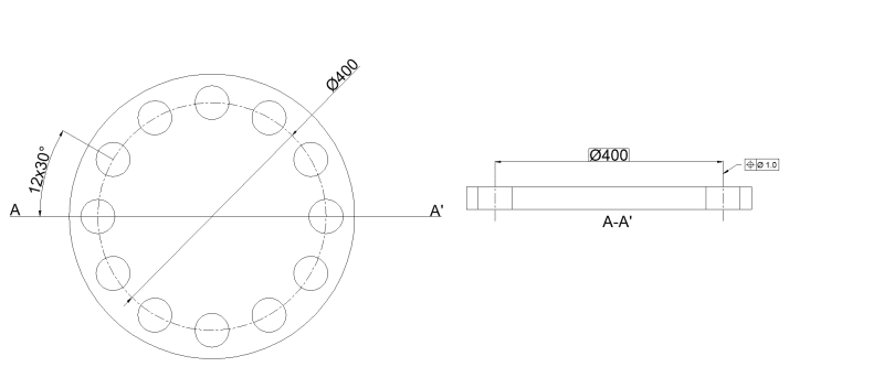
I realize there are numerous mistakes here, but please bear with me.
For the purpose of positioning tolerance of the holes, if I do the callout on a section (of two opposite holes), would the tolerance still apply on the other 10 holes in the remaining drawing?
Or does this generally fall under below statement?
Dimensions and tolerances apply only at the drawing level where they are specified. A dimension specified for a given feature on one level of drawing (e.g., a detail drawing) is not mandatory for that feature at any other
level (e.g., an assembly drawing).
I am confused by the example of the assembly drawing, as it is still the same part (not part of an assembly).
If this is not case, and it is allowed / has sufficient meaning. Where would you apply the datum?
On the plan view or the section view?
Then a second question I had. Looking at the 'proper' example in the standard:
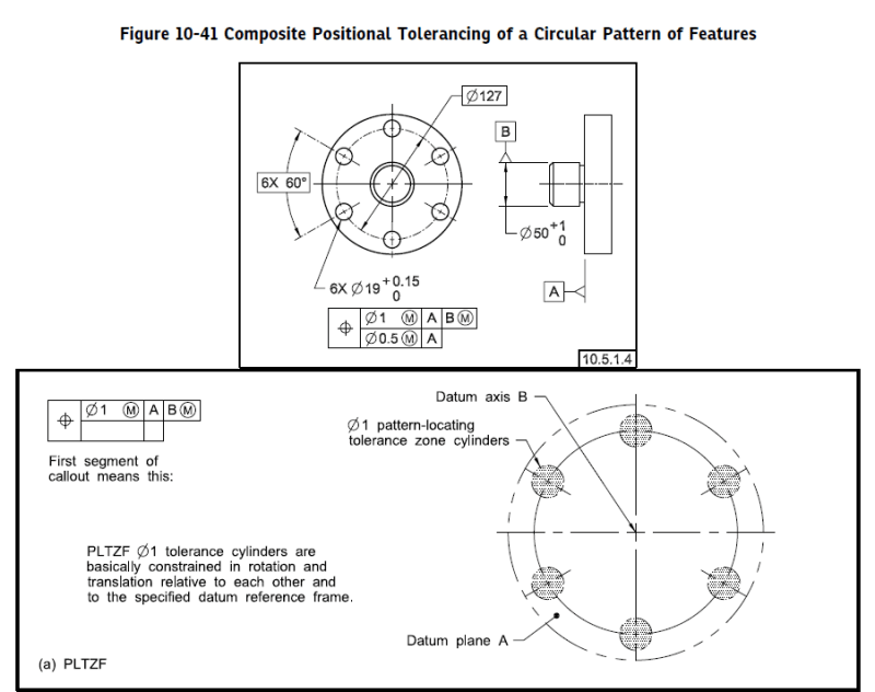
What part of the callout refers to the angular position of the holes, A or B or something else?
What controls the global angularity of the holes? Why can't they all be shifted 1° (from north) but still be 6x60° from each other?
Thanks in advance.
EDIT
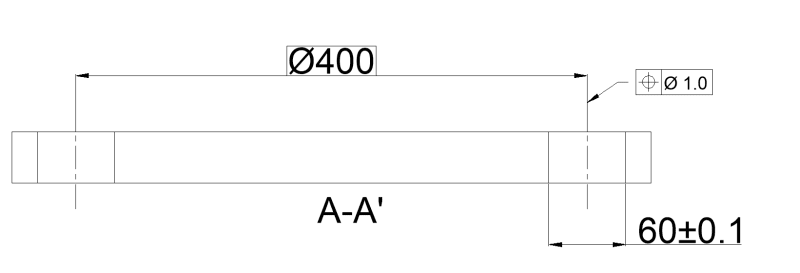
Another question, is it allowed to detail the diameter of the holes like below?
Would the position tolerance even be valid for the indicated centerline of the diameter.
Would the tolerance of the diameter (60+- 0.10) be valid for the rest of the holes in the plan view drawing?
I have some questions about position tolerance of a circular pattern.
Consider below drawing
I realize there are numerous mistakes here, but please bear with me.
For the purpose of positioning tolerance of the holes, if I do the callout on a section (of two opposite holes), would the tolerance still apply on the other 10 holes in the remaining drawing?
Or does this generally fall under below statement?
Dimensions and tolerances apply only at the drawing level where they are specified. A dimension specified for a given feature on one level of drawing (e.g., a detail drawing) is not mandatory for that feature at any other
level (e.g., an assembly drawing).
I am confused by the example of the assembly drawing, as it is still the same part (not part of an assembly).
If this is not case, and it is allowed / has sufficient meaning. Where would you apply the datum?
On the plan view or the section view?
Then a second question I had. Looking at the 'proper' example in the standard:
What part of the callout refers to the angular position of the holes, A or B or something else?
What controls the global angularity of the holes? Why can't they all be shifted 1° (from north) but still be 6x60° from each other?
Thanks in advance.
EDIT
Another question, is it allowed to detail the diameter of the holes like below?
Would the position tolerance even be valid for the indicated centerline of the diameter.
Would the tolerance of the diameter (60+- 0.10) be valid for the rest of the holes in the plan view drawing?