Continue to Site

Eng-Tips is the largest engineering community on the Internet

Intelligent Work Forums for Engineering Professionals

  • Congratulations KootK on being selected by the Eng-Tips community for having the most helpful posts in the forums last week. Way to Go!

Position tolerance on distance ( Basic dimension) 1

Status
Not open for further replies.

anbumanoger

Aerospace
Feb 7, 2020
1
Hi everyone,

when there is a position callout given on the dimension line which is 0.8mm position and the dimension line is the distance from the datum and its basic dimension which is 50mm. Now, what would be the tolerance for 50mm Basic dimension? 50±0.8 or 50 ±0.4mm.

Because when there is a position callout with Ø symbol then we have to consider half of the tolerance. but here it is a simple distance and only one datum hence I thought to have 50±0.8mm.

Please, someone, help me to understand this in a better way. Also please share if you have any reference.

Thanks in advance.
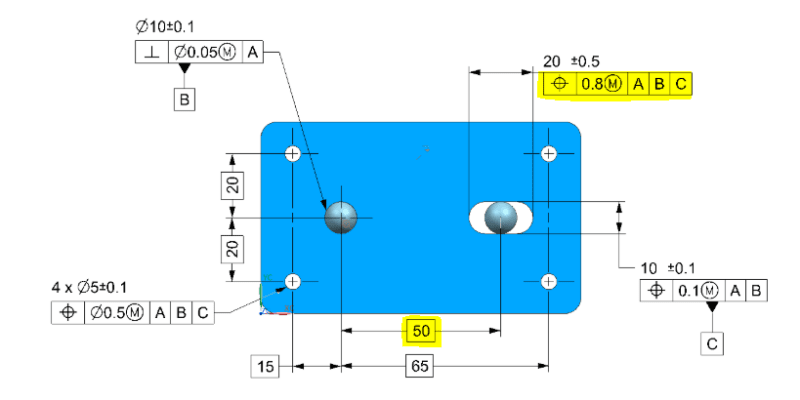
Capture_xnkp9n.png


Regards,
Anbu manoger.
 
Replies continue below

Recommended for you

This looks like a tec-ease tip, is this pursuant to Y14.5-2009?

what would be the tolerance for 50mm Basic dimension? 50±0.8 or 50 ±0.4mm.

Basic dimensions by definition are not toleranced. They are theoretically perfect dimensions which locate and orient tolerance zones relative to your DRF.

but here it is a simple distance and only one datum hence I thought to have 50±0.8mm.

The position tolerance applies to your feature not the basic distance. Where do you see only one datum/datum feature? I see position to |A|B|C| in the highlighted FCF, A being presumably one of the flat faces which the slot is normal to.

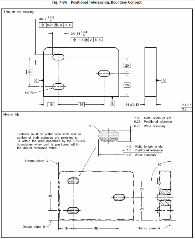
Y14.5-2009 has an example of this case with fig 7-34. The only difference being that C is the width of the slot in your example which makes the boundary slightly more difficult to evaluate (the figure in the standard has simultaneous requirements so the slot has one continuous MMC VC boundary. In your example the boundary of the length of the slot is separate, of a different looser tolerance and dependent on the width).

7-34_sfg7r4.png
 
The short answer is +/-0.4 but because you have a max material condition qualifier there is a bonus tolerance as well.

Position tolerance is always the size of a zone centered at the basic location.

I question the reasoning of using MMC in this case. At the MMC condition, the slot is at it's smallest size and therefor would need to be more precisely located, not worse. I think this should have a LMC modifier.

----------------------------------------

The Help for this program was created in Windows Help format, which depends on a feature that isn't included in this version of Windows.
 
dgallup, the LMC modifier will allow the slot to be less precisely located the closer it gets to being produced at MMC size.

 
dgallup said:
At the MMC condition, the slot is at it's smallest size and therefor would need to be more precisely located, not worse. I think this should have a LMC modifier.

I do not think we have enough info to say that. It is just pure speculation at this point.
You don't see the other view how this part looks like. We don't even know where datum feature A is. We might guess or assume, but it is not defined. (I am talking about the OP's drawing and not chez311's-from the standard)-

Maybe just fluid goes thru the slot, hence LMC might be the correct application. Never know.
 
Anbumanoger,

If on the drawing that you provided there was no (M) modifier after 0.8, the centerline derived from the 20 +/-0.5 width dimension could be <50-0.4;50+0.4> = <49.6;50.4> from the datum axis B.

Because (M) modifer is applied after 0.8, the centerline can be:
[ul]
[li]<50-0.4;50+0.4> = <49.6;50.4> from the datum axis B when the width has been produced at its MMC size = 19.5;[/li]
[li]<50-0.4-0.5;50+0.4+0.5> = <49.1;50.9> from the datum axis B when the width has been produced at its LMC size = 20.5;[/li]
[/ul]
With that said, it is still true that basic dimensions don't have tolerances. They define theoretically exact location and/or orientation of features/tolerance zones relative to the datum system (Datum Reference Frame). In other words, it is not the basic dimensions that should be verified. It is the deviation of the center of the feature from its true position that should be verified.

Just imagine that on your drawing the basic 50 dimension was changed to basic 15 dimension between the centerline of the two rightmost holes and the center of the slot. This wouldn't really change anything in the meaning of the position tolerance of 0.8 applied to the slot, but according to the logic that basic dimensions have variation, it would require including variation of basic 65 dimension in order to say how much the slot center might vary from its true position.
 
This is a common question... many people think that the diameter symbol in a position tolerance is what makes it a total tolerance which is then chopped in half for any given direction. But even without the diameter symbol, it's still a total tolerance which is chopped in half for one side or the other.
The short answer is that a position tolerance is always a total tolerance, which is disposed around the true position (basic dim). The diameter symbol, or lack of diameter symbol, only tells us whether the position tolerance provides 360º coverage or not.

John-Paul Belanger
Certified Sr. GD&T Professional
Geometric Learning Systems
 
deleted

----------------------------------------

The Help for this program was created in Windows Help format, which depends on a feature that isn't included in this version of Windows.
 
dgallup said:
Quote (Burunduk)

dgallup, the LMC modifier will allow the slot to be less precisely located the closer it gets to being produced at MMC size.


Say this slowly and realize the complete fallacy.


dgallup,

Could you, please, elaborate? I am not getting your point correctly.
Thank you


dgallup said:
I question the reasoning of using MMC in this case. At the MMC condition, the slot is at it's smallest size and therefor would need to be more precisely located, not worse. I think this should have a LMC modifier.

And the above Tec-Ease tip is also using MMC and not LMC

Are you questioning that too?
 
dgallup, no fallacy there.
For a geometric tolerance specified with an LMC modifier on an internal feature, the larger the internal feature is (closer to LMC) the closer it gets to the virtual condition boundary, and the less out of true position it is allowed to be. The smaller the slot is, the farther it is from the virtual condition boundary, and the more location/orientation variation allowed.

Perhaps the simpler way to explain it is with the bonus tolerance concept which you are probably familiar with.
The tolerance applied at LMC means maximum bonus tolerance for position at MMC (smallest slot).
 
I'm sorry, I was having a brain fart on which direction gets the bonus tolerance. I will edit my posts.

----------------------------------------

The Help for this program was created in Windows Help format, which depends on a feature that isn't included in this version of Windows.
 
Hello everyone. This is more of a question actually. By looking at the highlighted True Position on anbumanoger's drawing, how do you program that on the CMM. As far as I know True positions apply to only features of size and the CMM will expect you to plug that into the first field of the True Position main form. Distances are not features of size. Please help on this as I am doing a project similar to this--see attached and advise. Any help is greatly appreciated.
 
 https://files.engineering.com/getfile.aspx?folder=d35ce5e8-e20b-4d22-8734-f1f1bbf25f43&file=2020-03-06_23h35_34.jpg
The highlighted position tolerance is applied on a "regular feature of size", a concept that includes per the ASME Y14.5-2009 standard "a set of two opposed parallel elements".
 
Burunduk, the position FCFs on that drawing are not FOS of any kind -- notice the dims are coming from a center. So tainest77 has a legitimate gripe (I'm not sure where that drawing comes from... it's not anbumanoger's original posted drawing).
It's bad GD&T; no other way to say it.

John-Paul Belanger
Certified Sr. GD&T Professional
Geometric Learning Systems
 
Belanger, in his post in this thread, tainest77 asked about the OP post with the highlighted position tolerance applied on length of the slot:
"By looking at the highlighted True Position on anbumanoger's drawing..."
He thought that it has something in common with his case of position applied to non-FOS, hence my response that the tolerance in the OP of this thread applies to a FOS. On another thread tainest77 opened, I addressed his drawing too.
 
tainest gave two different questions - burunduck - your answer was entirely ambiguous as to which one it might apply to, and was not a proper answer to either of them.

1 how do you program that on the CMM. Your answer says nothing about it.
2 Please help on this as I am doing a project similar to this. Your answer is wrong if applied to this.
 
3DDave,
Read tainest77's question again, this time with paying attention. It is driven by thinking that the "[highlight yellow]highlighted[/highlight] True Position on anbumanoger's drawing" (exact quote) has the same issue that the drawing he is dealing with has (position applied on non-FOS). Look up in the OP for a "highlighted" tolerance. The relevance of my answer ("[highlight yellow]The highlighted[/highlight] [highlight #FCE94F][/highlight]position tolerance is applied on a regular feature of size") to the relevant question on which he focused in this thread is obvious, especially given that I already responded to his original question in the new post he opened by the time he posted here. It is up to tainest77 to say if anything in my answer was ambiguous.
 
Burunduk -- I know what he wrote, and I obviously looked at the first picture of this thread. It was NOT in any way the FCF that was attached in his post of 8 Mar 20 08:11. I think you jumped to the first picture of this thread, while I was looking at the attachment that he was asking about.
Sorry for the confusion.

John-Paul Belanger
Certified Sr. GD&T Professional
Geometric Learning Systems
 
Belanger, there is no "highlighted
true position" tolerance in his attachment. In this thread, he is asking about the OP, and referring to his own case which he thinks to be similar (hence the attachment), although it is not.
 
Status
Not open for further replies.

Part and Inventory Search

Sponsor