Continue to Site

Eng-Tips is the largest engineering community on the Internet

Intelligent Work Forums for Engineering Professionals

  • Congratulations KootK on being selected by the Eng-Tips community for having the most helpful posts in the forums last week. Way to Go!

Position tolerance on distance ( Basic dimension) 1

Status
Not open for further replies.

anbumanoger

Aerospace
Feb 7, 2020
1
Hi everyone,

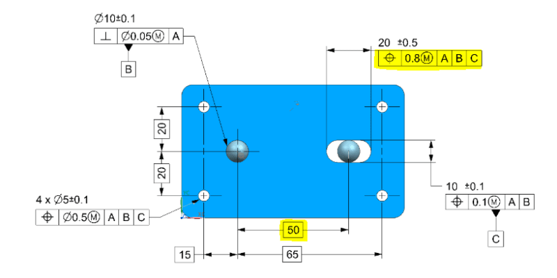
when there is a position callout given on the dimension line which is 0.8mm position and the dimension line is the distance from the datum and its basic dimension which is 50mm. Now, what would be the tolerance for 50mm Basic dimension? 50±0.8 or 50 ±0.4mm.

Because when there is a position callout with Ø symbol then we have to consider half of the tolerance. but here it is a simple distance and only one datum hence I thought to have 50±0.8mm.

Please, someone, help me to understand this in a better way. Also please share if you have any reference.

Thanks in advance.
Capture_xnkp9n.png


Regards,
Anbu manoger.
 
Replies continue below

Recommended for you

Guys, My sincere apologies for any confusion about my post. All of you has a point but it obviously seems like I was not too clear. Let me restate this once again:
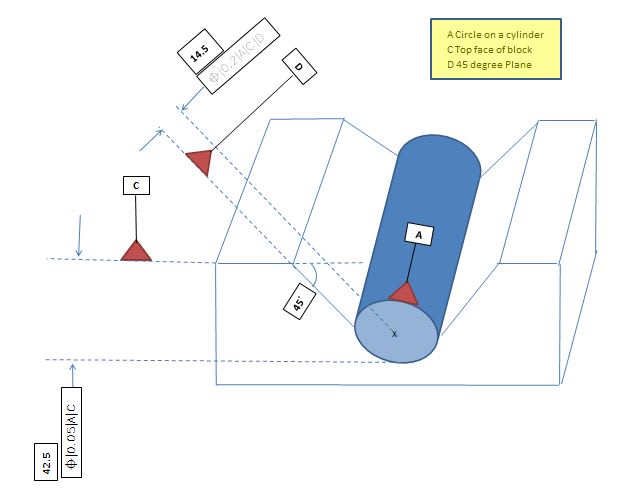
On 7 Feb 20 13:49, anbumanoger in his post(original post here), the TP associated with the width of the slot, I have a problem understanding it since the width of the slot is a distance and a distance is not a feature of size and therefore at least in ISO you can not apply a TP to a non-feature of size. I am not sure about ASME though. Now I have a situation similar to this of my own, Burunduk was trying to help me with. However the sketch I attached was also bad and unclear I think. In this post I tried to make another one but please bear with me--this is by no mean a complete or perfect one either. It's no more than a hand made one in Excel for illustration purpose only. My question now: Are these TP call outs legitimate call outs to begin with?--see my attachment please. and if so, how do you go about measuring/programming this with a CMM since both TP are pointing to what seems like a distance. CMM will not allow you to apply a TP to a distance!

PS: Mr. Belanger you were one of my GD&T instructor in Va Beach, VA. My Greetings to you Sir. Glad to see you here.

Regards,
3-8-20_uklvdk.jpg

 
The link has an "&" in it which needs to be replace with some hexadecimal to download.

In any case, the position tolerance in Y14.5 compliant drawings is never applied to a center line. It is applied to the surface of the feature that an axis or width is to be determined from.

I'm not sure what you are trying to control, but whatever it is, that is not an interpretable callout.
 
Copy and replace the ampersand in the URL for the file with %26. I think it will still look like an "&" in the web browser, but it will work to download it. If anyone wants to they can copy and past it into an address window and manually replace it before hitting the 'go' button.
 
Hi tainest77... in the original picture at the start of this thread, the two position tolerances are applied to "features of size." The two flat sides of a slot constitute opposing elements, and it is a directly toleranced dimension. It's no different than having a rectangular block where the height or thickness is dimensioned (and toleranced) and then a position callout is tagged to that dimension.
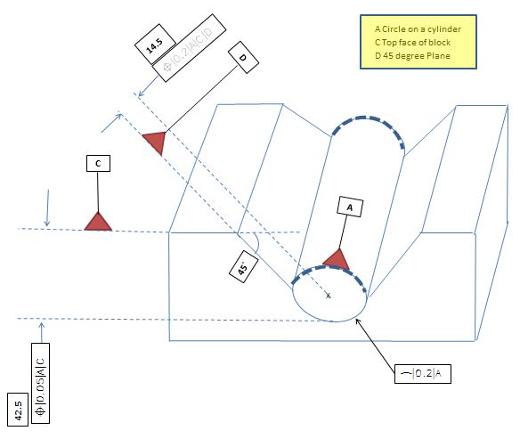
In your pic of a cylinder sitting in a V-block, we could change the 14.5 basic dim into a non-basic diameter of 29, and then your position tolerance would make sense.


John-Paul Belanger
Certified Sr. GD&T Professional
Geometric Learning Systems
 
The tolerance zone for the slot center is a rectangle 0.8 long by 0.1 high (plus MMC allowance), co-centric with the slot center.

[bat]Honesty may be the best policy, but insanity is a better defense.[bat]
-SolidWorks API VB programming help
 
Hello Mr. Belanger. Unfortunately in my V-block illustration the actual drawing matches what you see—the 14.5 is shown as a basic. How about the self referencing in the FRF of datum A?and how about the second TP callout? BTW this is using ISO standard.
 
I'm not sure how to answer your question because in both ISO and ASME, that is not a proper use of position. ASME requires it to be used only on a feature of size. ISO allows position for a feature of size or also a flat surface.
The only way I can envision that 14.5 being a legal basic dim is if a profile tolerance were being imposed on the cylindrical surface somehow.

John-Paul Belanger
Certified Sr. GD&T Professional
Geometric Learning Systems
 
Yes there is actually a line profile imposed on the front face (bottom 180 perimeter) of the cylinder--I left out in previous sketch. And also to clarify some confusion: Think of this whole V-Block and cylinder as a one whole single piece with the cylinder being an internal feature, meaning hallow instead of a pin per say. Also only the first bottom half of the cylinder exists, the top 180 is a dotted half if you will. Sorry I just attempted to sketch something similar to the actual drawing I am working on, since I am not allowed to post actual drawing here.


3-10-20_tst3i5.jpg
 
tainest77,

I would suggest you direct everyone to the thread you started on this exact topic ( It is very confusing following both threads. You've tried to indirectly address a question I had in the other thread in this one and it makes it difficult to respond.
 
Status
Not open for further replies.

Part and Inventory Search

Sponsor