Eng-Tips is the largest engineering community on the Internet

Intelligent Work Forums for Engineering Professionals

Positional Tolerancing Boundary Concept Angled Slot

Status
Not open for further replies.

rsm7400

Industrial
Mar 6, 2012
52
0
0
US
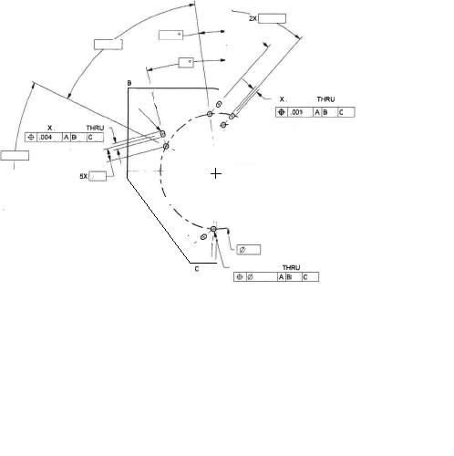
Im a little stuck on this one. I have some slots with a true position of .001 on the width but .004 on the length. The slots are at angles offset from a series of holes.

The holes also have a true position which was easy to check - Using polar coordinates the holes were checked to the basic bolt circle and basic angle positions.

Looking at the Y14.5-2009 fig 7-34 defines the boundary concept. Which I can wrap my head around when the slots are parallel to each other and the datum face. How do I interpret the true position in my case of width and length? I have attached the most detailed drawing I can provide - if it is not enough I can try to explain in writing more but cannot show more on the drawing.
Print_Help_bxsp62.jpg


________________________________
Ryan M
Quality Engineer
3d Printer Hobbyist
 
Replies continue below

Recommended for you

You use basic dimensions and geometrical tolerances provided to establish virtual condition - the area where no part material can go.
It's just more obvious with round holes, but the idea still the same.
See if the enclosed illustration can help.

"For every expert there is an equal and opposite expert"
Arthur C. Clarke Profiles of the future

 
 http://files.engineering.com/getfile.aspx?folder=2becd94c-2f51-498e-91bf-6656c1ff8ddb&file=Dimesioning_Guide_for_Slots.pdf
Thanks for replying so fast. That illustration is much better than the one I had on file. My only comment is, on my print it does not specify boundary, that was just the only section in the book that looked similar to me. If mine does not say boundary do different rules apply? I have set up inspection routines on literally 1000's of different parts, but somehow this is my first with 2 true positions called out on the same feature (the length and width of the slot).

________________________________
Ryan M
Quality Engineer
3d Printer Hobbyist
 
According to new standard (2009) boundary is now understood and doesn't have to be specified. Hope it helps.

"For every expert there is an equal and opposite expert"
Arthur C. Clarke Profiles of the future

 
rsm7400 said:
My only comment is, on my print it does not specify boundary, that was just the only section in the book that looked similar to me. If mine does not say boundary do different rules apply?


The BOUNDARY note/word is optional in Y14.5-2009

A.10.8 Boundary of an Irregular Feature of Size
The term “BOUNDARY” beneath the feature control frame
is now optional in an application where it is necessary to
control the boundary of an irregular feature of size.

 
Yup I think I can understand it better now. I will be inspecting this on a CMM that compares to a CAD file, however I wanted to make sure I understood it a little better so that if a part gets rejected I can explain it to powers that be.

Thanks for your assistance!

________________________________
Ryan M
Quality Engineer
3d Printer Hobbyist
 
7.4.5.1.

(c) In Terms of the Boundary of an Internal Feature of Size.
A positional tolerance applied to a feature of size establishes
a control of the surface relative to a boundary.
While maintaining the specified size limits of the feature
of size, no element of its surface shall violate a theoretical
boundary of identical shape located at true position.
The size of the boundary is equal to the MMC size of the
internal feature of size minus its positional tolerance. See
Fig. 7-34. The term BOUNDARY may be placed beneath
the feature control frames, but is not required.
[/b]In this
example, a greater positional tolerance is allowed for its
length than for its width. Where the same positional tolerance
can be allowed for both, only one feature control
frame is necessary, directed to the feature by a leader
and separated from the size dimensions.
NOTE: This boundary concept can also be applied to other irregular
shaped features of size — such as a D-shaped hole (with a fl attened
side) — where the center is not conveniently identifi able. See
para. 8.8.
 
Could this be interpreted as Bidirectional tolerancing per para 7.4.4 in 2009 (page 122). But is it by default BOUNDARY because of the radii on both ends (as opposed to holes or slots with "flat" ends)

Certified Sr. GD&T Professional
 
Status
Not open for further replies.
Back
Top