rsm7400
Industrial
- Mar 6, 2012
- 52
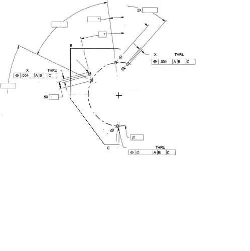
Im a little stuck on this one. I have some slots with a true position of .001 on the width but .004 on the length. The slots are at angles offset from a series of holes.
The holes also have a true position which was easy to check - Using polar coordinates the holes were checked to the basic bolt circle and basic angle positions.
Looking at the Y14.5-2009 fig 7-34 defines the boundary concept. Which I can wrap my head around when the slots are parallel to each other and the datum face. How do I interpret the true position in my case of width and length? I have attached the most detailed drawing I can provide - if it is not enough I can try to explain in writing more but cannot show more on the drawing.

________________________________
Ryan M
Quality Engineer
3d Printer Hobbyist
The holes also have a true position which was easy to check - Using polar coordinates the holes were checked to the basic bolt circle and basic angle positions.
Looking at the Y14.5-2009 fig 7-34 defines the boundary concept. Which I can wrap my head around when the slots are parallel to each other and the datum face. How do I interpret the true position in my case of width and length? I have attached the most detailed drawing I can provide - if it is not enough I can try to explain in writing more but cannot show more on the drawing.

________________________________
Ryan M
Quality Engineer
3d Printer Hobbyist
