Eng-Tips is the largest engineering community on the Internet

Intelligent Work Forums for Engineering Professionals

Positioning flow meter upstream or downstream a flow control valve 3

Status
Not open for further replies.

Muud

Materials
Nov 29, 2017
44
0
0
NL
The drawing below shows the future layout of our test system. For the position of the magnetic flow meter, I think if provided a few pipe diameters straight length upstream and downstream of the flow meter, it's location wouldn't affect too much on the flow measurement and ultimately the performance of the control loop it forms with the automatic flow control valve. However, I am not certain so would like to have your feedback regarding the best position of the flow meter. We need to control the flow rate at the test vessel inlet. At this point the set flow rate and the actual flow rate should be equal.

Flow_meter_location_ozabfb.png


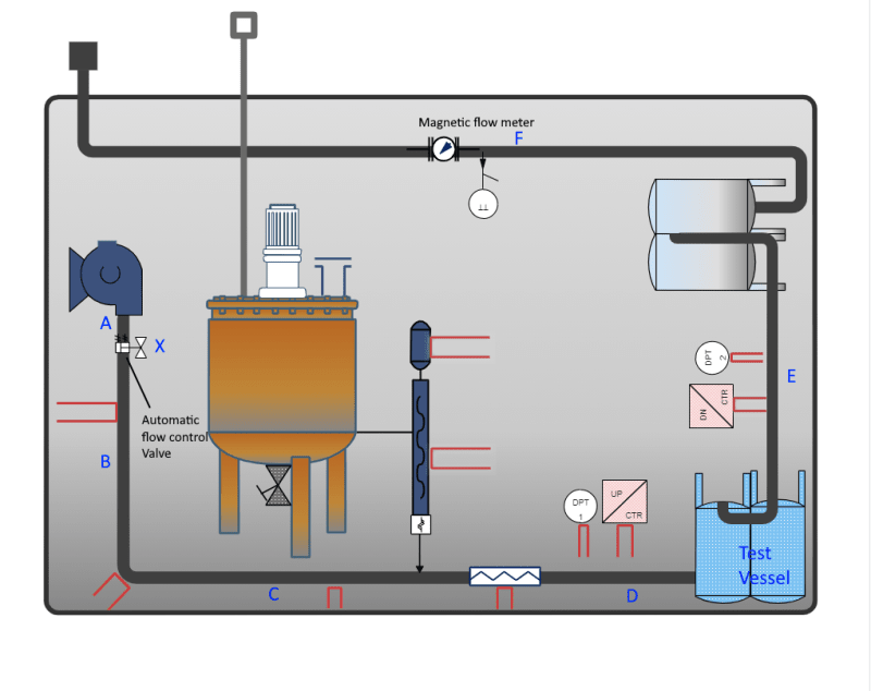
The possible locations marked A-F are shown on the drawing. X and F are the current positions. The location choices are basically either before or after the flow control valve. I wonder if installed further downstream (i.e. the vessels in between and long pipe length) there might be a delay and it may affect the flow control loop. What do suggest? Do you see any other issues?
 
Replies continue below

Recommended for you

You don't say what fluids you are using.

What is the tank looking thing after "E"?


Normally you want to see a minimum 10 diameters upstream and 5 D downstream on a horizontal run. Might be OK as is, or even better to shift it left.

A check valve might be a good idea to keep possible backflow from messing up the meter reading.

You may want a backpressure control valve downstream of the meter to help keep the meter pressure stable and free from wild and fast pressure variations. I dont know what the black box is after the meter, so hard to say if that might be needed.


The test fluid is water and the tank looking thing is just another vessel with filters.


I know it's not something standard but the black box represents the water reservoir instead of showing the whole big thing :)
 
But it looks like you're injecting something between C and D??

So a meter at X wouldn't measure the total where as it does at the F location.

but either looks ok to me so long as your actual pipe layout gives you some straight diameters or you can insert a flow straightener or similar.

a lot depends on how accurate you want this to be but a mag flow meter is pretty robust. See attached noting that you need to keep the pipe full and also avoid swirl from lots of changes in direction or stick in a flow conditioner plate upstream.
Remember - More details = better answers
Also: If you get a response it's polite to respond to it.
 
Several years ago, Siemens put their magmeter on a flow stand to test it for compliance with the European potable water distribution standard, ±2% accuracy, regardless of upstream of downstream piping elements.

Siemens has a 7 minute video showing the various combinations of elbows and tees that were used.
Link
The Siemens meter passed. Interesting to have an uncertainty value to associate with piping elements upstream or downstream of a magmeter, which had not been available previously. I recall that Toshiba made a similar claim for one of its magmeters about the same time.

I am mystified why the zero-up/zero-down (number of diameters up or down stream) claim is not asserted for all flow meters. How much do magmeter models differ from one another? They're all an open tube with a couple electrodes somewhere in the middle. How much could one magnetic flux pattern differ from a flux pattern in a different model?

To your point about location with respect to a control valve, is the swirl pattern and its effect on the flux from close coupled elbows and tees more severe, causing more error than the swirl from a control valve? Apparently so, because Siemens specifically states at 6:50 in the video that the test results do not apply to partially open control valves upstream of a magmeter (5th bullet point).

My opinion is to get the magmeter either upstream or as far downstream of the control valve as is feasible.
 

Great articles and video resources guys. Thanks :)


@LittleInch Yes that's correct. Between C & the test vessel a diluted slurry solution will be injected so X will not be a good installation location. Providing even up to 10 x pipe diameters wouldn't be an issue in our layout. Regarding the swirl issue, are you referring to the total number of directional changes upstream or just before the meter? In front of the meter there will be just a single 90 elbow whereas throughout the whole upstream there will be 7 directional changes.

@ danw2 I fully agree with your comments regards accuracy. I believe the current position (point F) should suffer least from the swirling and flow profile modifications. So would keep it like that.
 
@ 1503-44 I don't know a lot about the backpressure regulator valves but after a quick reading on the subject, I doubt it would be appropriate in this setup. It is a filter test setup. We test the filters by presenting them the challenge fluid at a constant flow rate and record the pressure drop created by the filter.

So wouldn't the backpressure filter interfere with the pressure drop that we intend to measure and oppose the working of flow control valve that serves to keep the flow rate constant during the test?
 

Actually you might be running a risk of blowing out or dishing the filter too.

Normally you want to maintain as near a constant pressures and flows as possible everywhere during measurement. Doing that nicely requires a constant source pressure (your pump) and a constant sink pressure (your reservoir). That will avoid flow and pressure surges. If your reservoir will hold a more or less constant pressure for all operating flow rate, then you wouldn't need a backpressure valve to do that. I dont know the details of the reservoir, so I can't say if it will act to hold a minimum pressure in your pipe or not. I also do not see a means of controlling differential pressure across your filter, or your system as a whole.

The system I see has flow control, yet you say you want to control pressure, specifically pressure across your filter when testing. Right now you will set a flow rate and upstream pressure will be whatever pressure it takes (providing that the pump can reach it) to deliver your set flow rate. Downstream pressure will be whatever the reservoir pressure is (when flowing your set flow rate).
Pump discharge pressure could vary, if your filter picks up particles, as it tries to keep your set flow rate. That might get guite high, potentially blowing out your filter. The downstream pressure is whatever the reservoir pressure is at the set flow rate. Neither pressure is being actively controlled. If that is the way you want to do it, leave it as it is.

If you want to control pressure drop across the filter, then change the flow control valve to control its downstream pressure. You will then have control of pressure upstream of the filter. If the filter picks up particles, the upstream pressure will not increase, potentially blowing the filter. So far, to control differential pressure across the filter, you can set upstream pressure, but downstream pressure will be your reservoir pressure. If the reservoir can control pressure satisfactorily by itself when testing the filter, you're good. If it cannot, then you will need a backpressure valve to do it. If you have a backpressure valve, then you will have positive control of the differential pressure across the system and hence also across your filter and the flow meter too. Otherwise that will be whatever the reservoir can hold on its own. It may be suitably stable, or not. A pipe discharging over the rim of a tank, might not work well, but some other arrangement might. I dont know what you've got there.
 
A back pressure regulator just creates a fixed back pressure upstream of where it is installed.

So in this instance it would be set at say 1 bar to make sure that the meter is at a relatively fixed pressure.

That's all it does. So as the flow and pressure increase it open a bit and if the flow slows down then it closes. It won't have an impact on your other control valve which is controlling on flow, but you could integrate both and just take the lowest value into the valve.

But another issue is differential pressure as mr 44 says so again this is an input into the low selector block so if it exceeds say 1.5 bar then it closes to restrict flow and DP

Remember - More details = better answers
Also: If you get a response it's polite to respond to it.
 
In short...

You can actively control flow with a flow control valve, but pressures will be whatever they must be to deliver that flow, provided the pump and reservoir can adjust to those pressures, or ...

You can actively control upstream pressure with a pressure control valve and let the reservoir pressure be whatever the reservoir allows it to be and flow will be whatever flow upstream and reservoir pressures allow. You have positive control of upstream pressure only. or ...

You can actively control upstream pressure with the pressure control valve and actively control downstream pressure with the back pressure valve and flow will be whatever that pressure difference allows. You can figure out what that flow will be, or what you want it to be and set those pressures accordingly.

If you can decide which is best for your testing purposes, then we're in business.
For doing accurate as possible testing, I'd think having both pressure control valves is the best choice.

Having a backpressure valve will also help you to keep the meter full and ready to run when you turn the pump on. You won't have to wait for it to fill up and get all the air out, etc. Easier to operate.


My preference would be D or E.
Will the flow vary at all during the run? if so then the reaction time between the flow meter and control valve will need to be factored into the control loop tuning constants.
I would also favor a set up where there was a pressure control valve after the pump to provide a steady supply, and then place the control valve after the flow meter, then you always know what the pressure in the meter is and that the line is full.

= = = = = = = = = = = = = = = = = = = =
P.E. Metallurgy, consulting work welcomed
 
@ 1503-44, Thanks for your detailed feedback. Perhaps it wasn't clear from my previous posts that the purpose of this test rig is to load the filter with contaminants at a constant flow rate. So we don't need to control the pressure drop across the filter. Rather we record the increase in pressure drop across as the filter gets loaded more and more while maintaining a constant flow rate. So we aren't actually controlling pressure.

Here is the layout with the reservoir

For_Peter_im01to.png


The water level in the reservoir during the whole test remains constant so its pressure should also be constant.

The discharge pipe arrangement is over the rim but I haven't finalized whether it will be immersed or terminate above the surface of the water. What could be the issues with discharge over the rim?
 

@LittleInch, thanks for the clarification regarding the backpressure valve. It will be a useful addition to the current system.

@danW2, I did consider installing it vertically. In the existing layout (as shown above), it is possible to install the meter vertically in the U-bend next to the reservoir. However, there wouldn't be enough straight pipe diameters before and after. Other possibility is to introduce another U-bend with enough clearance up & downstream. I am not so keen on introducing extra bends in the system and wonder if the gain in accuracy would be that great compared to horizontal installation but ensuring a full pipe.

@EdStainless, is your preference for D or E based on the meter proximity to the control valve and ultimately the reaction time or other reasons?
No, the purpose of the the flow control loop is to maintain const. flow despite the increase in pressure drop across the filter. The reaction time will definitely be taken into account for tuning.
 
>However, there wouldn't be enough straight pipe diameters before and after. Other possibility is to introduce another U-bend with enough clearance up & downstream. I am not so keen on introducing extra bends in the system and wonder if the gain in accuracy would be that great compared to horizontal installation but ensuring a full pipe.

Your stated goal is "constant flow rate". That means repeatability is more important than accuracy. Does it matter if the indicated flow rate is off by 1% or 2% from what NIST would measure the flow rate at? I doubt it. Don't worry about the lack of straight runs.

Disclosure: I am neither an accuracy freak nor a metrology nut.
 
I feel as long as you have a backpressure valve or otherwise keep the meter full, you do not need vertical placement for accuracy. I know of NO vertical custody transfer meters used in any oil or gas pipeline ever and I've seen quite a lot of those. You will do much better keeping meters away from flow disturbance of any kind, especially upstream, but there are limits downstream too, just a lot shorter. I would worry about any lack of sufficiently long straight runs. There is a reason that gas companies machine bore their meter tube internal diameter down to 0.001 inch tolerance. There is no tolerance for errors when a company's daily billing can hit $5 to $10 Billion.


Thanks for the suggestions.

I don't think 1% deviation should be an issue but I prefer the horizontal installation with a backpressure valve and avoid a new U-bend.
 
Status
Not open for further replies.
Back
Top