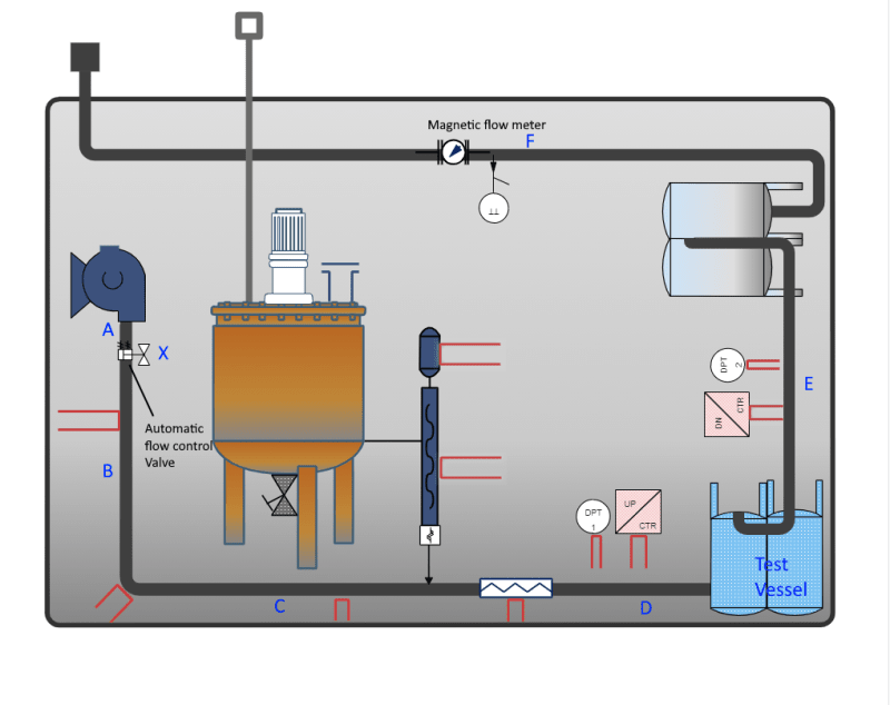
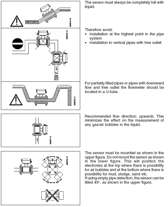
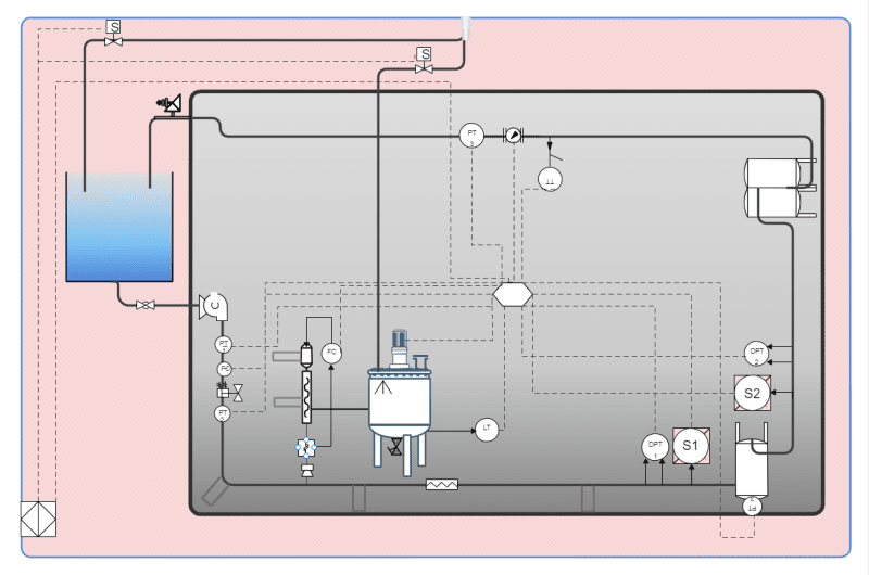
The drawing below shows the future layout of our test system. For the position of the magnetic flow meter, I think if provided a few pipe diameters straight length upstream and downstream of the flow meter, it's location wouldn't affect too much on the flow measurement and ultimately the performance of the control loop it forms with the automatic flow control valve. However, I am not certain so would like to have your feedback regarding the best position of the flow meter. We need to control the flow rate at the test vessel inlet. At this point the set flow rate and the actual flow rate should be equal.

The possible locations marked A-F are shown on the drawing. X and F are the current positions. The location choices are basically either before or after the flow control valve. I wonder if installed further downstream (i.e. the vessels in between and long pipe length) there might be a delay and it may affect the flow control loop. What do suggest? Do you see any other issues?

The possible locations marked A-F are shown on the drawing. X and F are the current positions. The location choices are basically either before or after the flow control valve. I wonder if installed further downstream (i.e. the vessels in between and long pipe length) there might be a delay and it may affect the flow control loop. What do suggest? Do you see any other issues?


