Eng-Tips is the largest engineering community on the Internet

Intelligent Work Forums for Engineering Professionals

  • Congratulations waross on being selected by the Tek-Tips community for having the most helpful posts in the forums last week. Way to Go!

Pressure and force in pumping concrete along a line to a piling rig. 2

Status
Not open for further replies.

WEBALL

Industrial
Mar 19, 2006
20
0
0
GB
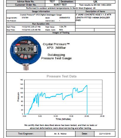
HELLO, WE have supplied a large amount of 5" concrete pumping hose (MWP 100 bar - TBP 200 bar.
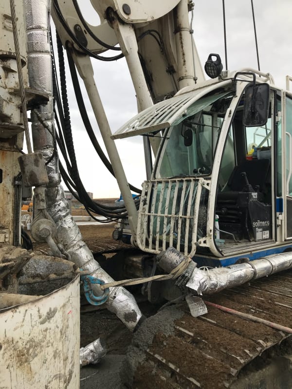
It has been fitted to a stationary concrete pump that pumps concrete over varying distances to a Piling rig up the mast and down a flight Auger (CFA Auger.
This is a VERY HIGH SAFETY issue.
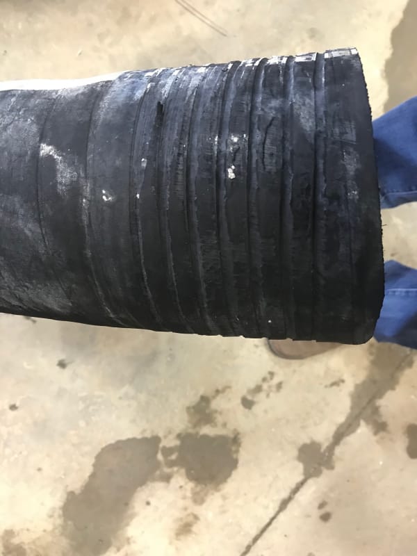
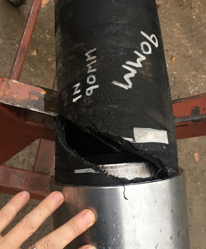
Within 6 months they have had two ends disconnect from the hose. Be it called 'blown off' or 'forced off'.
I can post the user report, but names are mentioned and first I would like to confirm my suspicion.
I have already advised to withdraw all hoses and place them on a pressure test.

The hydraulic power cylinder is 80mm bore with relief valve pressure set at 330 bar. they are directly pushing a 7" diameter concrete piston (steel rod connection)stroke 55". there is a short steel reducing pipe to 5" bore, this is then the start of the flexible hose line can be 20-30 mtr to the rig then vertical up the mast 15 / 20 mtr.

The set up worked for 4 - 6 months (289 piles bored and filled) this is not a lot of work.

The first failure was directly at the pump (1st hose-1st end) this was replaced with a new hose. the 2nd hose failed the day after at the base of the mast directly in front of the driver. These failures are 'explosive' as air in the concrete is compressed.
They have contacted the pump supplier (brand new pump) large international supplier and they have stated it is impossible for the pump to exceed 65 bar concrete pumping pressure. So the failure is due to bad hose and or bad fittings.
These failures can KILL.
When a blockage happens (I am told there have been lots of blockages) from a independent site visitor. I believe the hydraulic pressure / force is delivered direct to the point of the blockage in the 5" line. I calculate this is 131 bar.
Prior to the relief valve being activated.
I am working on a 'frictionless' calculation as I do not wish to complicate the issue with 'slump' 'friction' 'temperature' calculations.
I have sent an email with my 'worries' to the pump manufacturer as I say they are misleading 'users' about safety and pressure. this is promoting an "invunrability" feeling to users. So far they have not replied to my email.
We have done thousands of these hoses and not had reports of failures. I am very confident our product is good and calculations correct, but we are up against a very large multinational company. I have stated this is not to apportion blame but to work together to gain safety.
I have done pressure and tensile tests to confirm calculations on video, but having a problem with getting my point across.
I am hoping for someone with greater knowledge on hydraulics (a third party) to confirm if I am correct or not.
thank you.
 
Replies continue below

Recommended for you

On the basis that your 80mm hydraulic piston acts directly on the 7"piston, the maximum static pressure the pump can obtain is about 66 bar at 330 barg hydraulic pressure. The size of your pipe is not relevant.

However this is static pressure. Concrete pumping and piston pumps, often only two cylinders, can create large transient pressures which could be creating fatigue loads on your end coupling.

Shock loading might be an issue but not possible to tell from a distance.

66 bar end cap force on your hose is about 8 tonnes. What do you test the axial pull force on the end connections to?

Remember - More details = better answers
Also: If you get a response it's polite to respond to it.
 
Thank you for replying,
I have video of 10.2 ton on a dry end tensile, this was max length of stroke on the test rig 328mm.
I have also had a test piece under pressure of 100 bar for 7 days and nights, then increased to force the end off.
this a complicated test as the previous 7 days took all the 'stretch' out of the hose. this video is on Linkedin.

From your reply I take it you do not agree with my calcs that the blocked end on the 5" hose is 131 bar ?
The system becomes a totally hydraulic one when a blockage happens, Pascal says equal pressure in all parts of the system.
if you can reduce pressure going from 80mm to a bigger bore (177.8mm) you must increase it again if you reduce the bore to 5" is is on enclosed space.

330 bar at 80mm equates to 16.87 tons
330 bar at 7" equates to 66.8 bar (blank end area pressure)
330 bar at 5" equates to 131 bar

If as you say the size of my hose is not relevant, why do manufactures make hose that burst at over 200 bar (I have done this) when they could get away with making one to just 120 bar and make twice as much profit.
I have recorded video tests with data-log gauges to proof these figures, please can you ask me something that I can do to 'disprove' my findings.
thank you for quick reply.
peter
Pressure_to_tons_tensile_330_ocpwhe.jpg

Pressure_to_tons_tensile_330_-_divide_to_7_inch_i4rdjy.jpg

Pressure_to_tons_tensile_330_-_divide_to_5_inch_jjtsvi.jpg
 
I have done quite a bit of concrete pumping with 5 inch lines and have also experienced explosive failure at the hose ends on two occassions. I agree this is a fatality waiting to happen. My immediate comments are, the end user is making life difficult for himself by using all rubber hose , rather than maximising purpose built steel lines. Blockages are more frequent with hose than with steel pipe. Friction is way less than with steel pipe which implies pressure MIGHT be less but I cant comment on if this is valid. As I remember there are two separate hydraulic pressure gauges on the pump which give the operator a good understanding of how the system is operating but these values do not relate to the line pressures.

My experiences were 15 years ago and memory aint what it used to be but I do remember identifying a number of defective hose ends. These ends had clearly been crimped on to the hose , but there was a clear visual difference on the degree of deformation evident on the deformed end piece..... high deformation was good , low deformation was a dangerous situation.

I used a number of different pumps and altho I cant remember the details I would tend to agree with the pump suppliers, these units will not over pressurize properly fabricated hoses. I also used some 2 inch hoses and did not dramatically alter our operating pressures.

Are your hoses of foreign manufactuture??
 
Hello Mining man, Thanks for the input.
There are quite a few things going on here and your point about steel lines are correct, we have also done thousands of mtr of them.
I have been crimping hoses since 1993 and now can crimp up to 24" all my calc's are to same formula just the change of grip for different shore hardness of the rubber.
Most hose is made in Italy, but it is not the different manufacture. At the end of the day the material is 'elastic' that is why it is used on piling sites as the rig needs to move quite often to do a series of piles.
We can put screws through the crimp to the tail (which I am going to do) but this builds an even bigger danger to user's.
If you make users invulnerable they push the equipment farther to gain bonus.
The pump man was talking to the rig driver 30 yards from the pump when it blocked at the auger. He had to run to shut the pump down, all the while the relief valve coming on and off as the pistons tried to pump more into the line.
From my experience this then becomes a 'closed hydraulic system' the flex line being long makes it more explosive as more air is compressed. I have know some users to use extra long lines and keep the concrete moving back and forth while the rig re-positions.
We supplied two clients with the same batch of hose, same fittings, same fitting procedure, one user has had two failures the other none and over a longer time period.
I have a large jetting pump and burst short lengths at over 200 bar (equivelent to 30 ton tensile). The test piece we put on for 7 days at 100 bar slowly stretched so we kept topping up to 100 bar. after 7 days+nights we decided to see what it would take, it pushed off slowly at 104 bar (I expected this) as we had used up all the elasticity.

So when I am told the pump 'cannot' pump at more than 66 bar It makes me explore all possibilities. My findings are that at the time of the blockage the pump runs up to relief valve pressure "330 bar" at this point in time it is an 'Hydraulic' system as per Pascal's Principle. When a force is applied to a contained, in-compressible fluid, the pressure increases equally in all directions throughout the fluid. ... Since the pressure is transmitted equally throughout the fluid in all directions according to Pascal's Principle, P1 must equal P2 (psi calc's to the area of the blank) 5" = 131 bar ... 31 bar over max working pressure.

I have seen blockages cleared in hot climates where a 'slug' has formed at joints due to the concrete drying out. I have seen 'flash-overs' that have taken a full 100 mtrs in a matter of minutes. This one I think has 'frozen' in the line.

I am working on a gauge that will show both pressure and tonnage in a concrete line. In oil lines we set 'dry-breaks' this is not possible with concrete, but a 'wet-break' would be safer than a high pressure burst. Any one is welcome to visit to witness tests.
thank you.
 
Ok, Merry Christmas to you.

First off let's get the pressure thing sorted out.

You're halfway there already

"330 bar at 80mm equates to 16.87 tons
330 bar at 7" equates to 66.8 bar (blank end area pressure)"

The issue here is that pressure = Force/area.
For a piston, the only area that matters is the area of the face of the piston - in your case 7" diameter.
Once pressure is imparted to the fluid it can't magically increase.

If your PISTON AREA was a 5" piston then yes, you could get 131 bar, but it isn't, it's 7 inches. The force from the hydraulic piston is divided across those 38.5 square inches (7"), not 19.6 sq in (5").

Your hose though is more interesting and less straightforward. Hose and flexible design is much more art than science. Steel tube design has been studied for centuries, the material is ductile, has known properties and established limits and factors of safety.

Hoses and flexibles are much less studied, the materials are a mixture of types, sometimes they exhibit creep behaviour or non elastic behaviour and are a complex and everchanging design.

Hence establishing a reliable design limit is more difficult. Most hose and flexibles seem to work on a static burst pressure which is then divided by a factor of between 2.5 to 3.5 to establish a Max working pressure. Static testing cannot really simulate the actual conditions the hoses work under, with axial forces, bending moments, transient pressure pulses and other "shock" loading hence the large FoS used.

Your information to me says your 100 bar hose rating is actually set too high. With a factor of safety of only 2 plus the fact that at 100 bar the hose apparently yielded or has crept under sustained pressure - you describe this as having the "stretch" taken out of it, plus for the 100 bar test you had to keep putting more fluid in and then the burst pressure was only 104 bar after 7 days. I would term that excessive pressure myself and clearly shows the hose is yielding / failing over time at 100 bar.

SO are you the designer of the end connection? Can you post a sectional view?

Now why these hoses failed and other didn't seems to more about how they are operated and the forces being imposed on them. If there is more line and the pressure pulses from the piston are higher pressure than other locations then your end connection is simply easing off slowly over time. maybe. Either way from the data you've provided I really don't believe your 100 bar hose truly is a 100 bar hose. More like it has a Normal working pressure limit of 50-60 bar, with occasional transient pressure of 100 bar, but not a sustained pressure rating.

I realise this won't really help you, but that's how I see it from the data provided so far.

Remember - More details = better answers
Also: If you get a response it's polite to respond to it.
 
Hello LittleInch, happy Christmas.
Thank you, Yes I am a designer of hose ends, and a lot of years at it.
You are correct these hoses are NOT designed for 'sustained' pressure they are designed for pulse pressure (material handling)the tube (inside liner) is natural rubber, this is to resist the aggressive media.
Concrete pump hose is made by 'Spiral winding' of steel tyre cord on the mandrel at 55° 4 layers two each way. optimum bust angle is 45°.
The 10° is there to take the shock load/pulse. Spiral wound hose can stretch, A cross braided hose (hydraulic)is made more for sustained pressure. these are quite different constructions.

I think you have just highlighted the problem, Both our figures are correct, what is being lost is the 'way' the pressure leaves the pump and the way it is explained to the 'users'.
We both know the pressure cannot 'magically' increase..... BUT .... there is only 'one' power source.. -the pump-

These ends do not fall-off/drop-off and will not 'creep' with surge / pulse pressure to 100bar.
The 100 bar has only come in on the last several years, all concrete pump hoses used to be rated at 85 bar maximum working pulse pressure.
the hose we use used to be 2.5:1 (212.5 bar) under burst test condition would go between 220-240 bar.

One manufacturer (and there are many) decided to use a marketing ploy of saying 100 bar max working with a 2:1 safety. unfortunately this has been taken up now by most as some lost market share. Most now have two specs of hose ... 85 bar with 2:1 for 'land line' and 100 bar with 2:1 for mast hoses.

This has then dominoe'd to pump manufacturers and they lifted pump sizes / relief valve settings. This is a little of the history.
Back to the pressure problem. We do not have a 7" blank end (they can only call it that when they DO blank the end to test the pump.
What is being lost is that in 'operation' there is no 7" end there is a 1.5 mtr long tapered steel pipe down to 5"
direct from the concrete hopper/chamber.
So you have a 80mm hydraulic cylinder @ 330 bar then a 55mm steel rod pushing a 7" blind .... but ... this is a two piston pump, as one stroke pushes the other is pushing back on the annulus side to fill for the next stroke.
so this is increasing the hydraulic area by 4.11" giving 25.76 ton at 330 bar
In a 5" bore this is 200 bar.

66/67 bar is just not sufficient to push these ends off, it just does not happen.
there are 100's of crews working with the same hose / same ends and many with the same pump manufacturer.
I have duplicated as near as possible the failure 'figures' with no movement at all. I have had to exceed maximum safe usage by a huge factor before I have had a failure.
Yes, the hoses are 'elastic' they are meant to be, so if you do over capacitate them, they will fail.

I feel as you say, the operator is evading some answers to actions, or covering up on miss-use.

W.E. can send you a cross-section of the crimp, I need to do from work next week, but here is a picture of a failed end.
I can put screws through the crimp that will either pass the failure to the next weak point (burst the hose) this is more dangerous, or it will find the next weak point in the system.
I am not keen to do this, there are too many things I am not aware of.

Push-off_hose_end_mcoih3.jpg
 
Ah ha, things are becoming clearer. I was reluctant to provide additional suggestions because all my previous experience was with pumps utlising 5 inch pistons. Posts suggesting that this problem originated with 7 inch pistons made me think this was a new generation of pump that I was unfamiliar with. It now seems wethat this is not the case. Since we are now looking at operator error / poor training . I offer the following.

Having an operator 30 metres away from the pump is extremely poor practice. A competent operator watching the gauges can get a warning as to impending problems, sufficient to institute corrective action. And the absolute worst thing to do when a blockage occurs is to hit the emergency stop. The correct course of action is to immediately hit the reversing switch which instantaneously
reverses the pump direction with a corresponding drop in line pressure.

As the supplier of the hoses , the OP might have a difficult time diplomatically telling the end user that his men need proper training, but thats what it looks like to me.
 
And if I am to offer additional comments , I would want to know what is the size of aggregate in the concrete, design compressive strength of the concrete, at what stage during the pumping cycle are these failures occuring , is the line being properly slicked prior to the introduction of concrete. slump value of the concrete and how much super P is being used.
 
Thank you Miningman, Happy Christmas.
I will blank out the names/ companies involved and download what I have been sent.
I also think it is operator error, but I still struggle to explain the ends failing with the tests I have done. There is only one source of power, and 65/68 bar is not a big pressure for these hoses or fittings.
When the fittings are crimped we take them to maximum displacement, we stop as the tail inside starts to reduce in size.
I do have vague details of the concrete, but this only given a week or so after the below statement.
May I do the same with you please. My experience of slump and mix is not great.
My main aim on this is to learn and make the equipment better/ safer. We fitted up a short piece of hose from the same batch and same fittings, but purpos
Movment_at_130_bar_burst_at_135_bar_rnwzv1.jpg
sample_burst_short_crimp_135_bar_c9pegx.jpg
ely crimped one end not fully in to create a crimp not as good as it could have been on test it took 135 bar to burst the hose at the weak crimp end.


Ground Hose – November 13, 2018
• On Nov 13th one of the ground hose ends blew off. The end that failed was attached to the pump.
• Rig and pump set up on the day (starting at the pump) - ******** concrete pump - 40m long ground hose – 6.6m long steel catwalk piping - 4.6m long cab hose - 7m long steel mast pipe - 20m long hanging hose between the mast piping and swan neck. The drill rig was a SR65 with 19.5m of auger and a 6m extension.
• The outside temperature was ~ +6°C at the time of incident.
• This ground hose has been with this rig since it was purchased. So it would have been used to install 289 piles.
• We were just starting to concrete the second pile of the day. We were not aware of any blockages as the first pile poured fine, the move between the first and second pile was timely and there was no delay waiting for concrete. The crew said the hose blew immediately after kicking the pump on (2 pump stokes).
• The pump operator indicated the pump was reading a hydraulic pressure of 3,200 psi when the line failed, this would correspond with an approximate concrete pressure of 50 bar (725psi) based on the manufacturers documentation. The maximum concrete pressure is listed as 65 bar (942psi) for this pump.

Cab Hose – November 14, 2018
• On Nov 14th one of the cab hose ends blew off while starting the concreting phase of the pile installation. The end that failed was attached to the catwalk piping.
• Rig and pump set up on the day (starting at the pump) - ******** concrete pump - 20m long ground hose – 6.6m long steel catwalk piping - 4.6m long cab hose - 7m long steel mast pipe - 20m long hanging hose between the mast piping and swan neck. The drill rig was a SR65 with 19.5m of auger and a 6m extension.
• The outside temperature was ~ +8°C at the time of incident.
• This cab hose has been on this rig since it was commissioned this summer. This rig has only installed 289 piles.
• We were just starting to concrete the second pile of the day. We were not aware of any blockages as the first pile poured fine, the move between the first and second pile was timely and there was no delay waiting for concrete. The crew said the hose blew immediately after kicking the pump on (2 pump strokes).
• The pump operator indicated the pump was reading a hydraulic pressure of 3,200 psi when the line failed, this would correspond with an approximate concrete pressure of 44 bar (640psi) based on the manufacturers documentation. The maximum concrete pressure for this pump is listed as 65 bar (942psi).
Image_2_a7ehrq.jpg


Thank you for your time on this, your comments are highly valued, Both Miningman and Littleinch.
 
Well I suppose there are two totally different possible lines of investigation here. One would relate to theoretical hydraulics and results of lab tests etc, the other would relate to field practices etc. One of the problems with the former is that it essentially assumes a system in equilibrium , at least to the point of incipient failure.

I quote "• We were just starting to concrete the second pile of the day. We were not aware of any blockages as the first pile poured fine, the move between the first and second pile was timely and there was no delay waiting for concrete. The crew said the hose blew immediately after kicking the pump on (2 pump stokes)

To have this sentence on both failure reports , IMO, is a major hint. Something is changing between the completion of one pile and starting the second. What time frame are we talking here??? What steps are being taken to prevent the rheology of the concrete in the line changing, or is the line being flushed between piles?? Is the start up , slow and steady at reduced pressure untill flow is established or is it " full hydraulic pressure immediately upon call for concrete???

Who is converting 3200psi hydraulic pressure to 650-725 psi line pressure and how confident are we in these values.?? I dont know how to make those conversions , but I do know the pumps I used maxed out at around 2400 psi hydraulic. Normal running was 1600- 1800 psi and as soon as 2100 showed on the gauge it was sign of an imminent blockage and time to reverse the pump rfn.

On one job I was pumpimg thru 800 feet of steel line. Some initial difficuties getting flow established but after that no major problemo.
 
"So you have a 80mm hydraulic cylinder @ 330 bar then a 55mm steel rod pushing a 7" blind .... but ... this is a two piston pump, as one stroke pushes the other is pushing back on the annulus side to fill for the next stroke.
so this is increasing the hydraulic area by 4.11" giving 25.76 ton at 330 bar
In a 5" bore this is 200 bar"

In concrete pumps the action of one cylinder filling whilst the other empties is separate. There is no increase in hydraulic area and NO increase in static pressure above 66 bar for a 7" piston. I repeat, the size of the hose has no impact on pressure. Please accept this as elementary physics and start looking for other reasons your hoses have failed.

Miningman - the "conversion" of hydraulic pressure to concrete pressure takes place as the diameter of the connected pistons between hydraulic end and concrete end increases (80mm / 3.1" to 7 "). The force from the hydraulic end is essentially spread about a larger area resulting in lower pressure.

Now I say static pressure for a reason. I think that your system is suffering from high impulse loads caused by a vacuum developing in the high vertical leg. When you reapply flow the concrete is closing this vacuum up very quickly and hence you have two high density fluid elements hitting each other at some velocity. This can give you peak pressure pulses of easily 4-5 times the static pressure.

Also when by the look of it when you say the hose end fell off, it doesn't look to me like the hose and the coupling came apart, but that it failed at the point where the hard fixed coupling suddenly changes to the hose. This is peak stress concentration territory and especially if there are no bend restrictors then it is not surprising this is the point of failure. I would recommend that the first 1m of hose is kept absolutely dead straight before any bending.

My suggestion for operating procedures is that on re-start with a full pipe of concrete, the pump is started as slowly as possible for ~ 30 seconds to close up any vacuum gaps and then slowly increased in pumping speed, if this is possible for the pump. If you ask about how they re-start might get you some interesting answers. I think miningman is having similar thoughts on the speed of start up.

Remember - More details = better answers
Also: If you get a response it's polite to respond to it.
 
WEBALL, I concur with Littleinch's comments regarding hose geometry at the base of the tower. I couldn't articulate why I don't like it, but Littleinch's suggestion, or at least a long sweep 90 degree elbow would eliminate my concerns. I have to admit that I have zero experience with piling but I do know that pumping downhill is a lot more problematic than pumping against gravity. And there was something about having a long vertical hose on the hose discharge that concerned me , but again I couldn't articulate why. So yeah , Littleinch's suggestion regarding vacuum makes sense, and yes, slow, low pressure at restart up is just good practice at all times. Of course all of this is leading towards poor operating practice as the root cause. As a lowly equipment supplier, trying to defend the integrity of your product, you and the end user may want to engage the services of an experienced independent pumping specialist to provide review and recommendations on the existing operating techniques.

Having said that , perhaps it would make sense to inquire as to any possible changes in the chain, since almost 300 piles appear to have been sucessfully completed. Any personnel changes at the batch plant or pump?? Any reason to think the mix design has changed, either deliberately or inadvertently?? Is air entrainment or Super P being used in ideal quantities. Has the overall length of pump hose increased??
 
PLEASE STOP THIS POST ... There is a reply missing I made to Miningman with details of the pump and a proposed question to Little inch.
This is a large amount of missing information.
I will try go back to my post to Miningman as it was extensive. thank you
 
There is something wrong with this thread, I made a big reply to Miningman with attachments.
the attachments where the details company specs of the concrete pump. and pictures.
I can remember most but I will need to post again.
Can I ask please did either of you receive a post that had "Occam's Razor" in the last few lines ?
 
Never saw it either. Maybe the site was doing some maintenence during the quiet period?


Remember - More details = better answers
Also: If you get a response it's polite to respond to it.
 
Hello Littleinch - Miningman,
My reply to Miningman was approx 8:00 and 9:00 am on the 28th with the full spec of the pump and a reply from a third party that visited the site and witnessed a lot of blockages.

Littleinch you must have seen part of the reply as you have made comment on the two cylinder rod adding annulus side to piston size yet it does not show my post above proposing this.

** it mixes things up a little and will mean me going over - re sending details. But I will reduce size of files.
(not sure if there is a way of asking the administrator for lost sections of threads).

My reply to Mining man was a copy of an email from site visitor, this is it :- below
[highlight #FCE94F]""I agree, as I have said previously, I don’t think we have got the full story of exactly what happened in both these failures, nor do I think we ever will.

During my time on the project they did not have a dedicated pump operator stationed at the controls of the pump, one of the crew would start pumping and walk away to the rig, when there was a blockage (which was often, as I recall 5 out of 6 attempts) he would run back over to the pump and stop the pump. Bad practice was most certainly occurring during my visit.

This type of pump can be set up rod or piston side, one higher pressures than the other, one for vertical distance the other for horizontal distance.not sure how Roterra pump was set up, no one ever checks this.

As I have said before, I do know they have had a lot of blockages due to their inexperience""[/highlight]

The pump manufacturer has not relied to my email and it has been a month, I do not have first hand experience with pumps, this one I am told was brand new. I do not think there is anything wrong with the pump, but I wanted their feedback in the interest of safety and correct operating procedures.
The pump is a Schwing SP 1250
I have attached a single sheet of the pump specs it is a PDF file.
I have had to put more than twice the 'energy' into the 5" line to get the hose to fail, even on a part crimped end. there is something happening that I am not aware of.
I will post more later.
 
 https://files.engineering.com/getfile.aspx?folder=e4458e24-d634-478a-8f44-7cfb8526c9c6&file=P-CUT-OFF_SP1250_2017_New_Gen.pdf
WEBALL:
To add to LittleInch’s and Miningman’s posts, there will also be some funny and indeterminate pressure pulses, thrusts, forces/stresses and hose movements around and either side of any direction changes, elbows and the like. I would make some length of straight solid pipe at these locations and then the coupling to hose, on the straight. I would be inclined to make as much of the total run solid pipe (not flexible hose) as I could, and carry the solid pipe a length or two away from any size or direction changes. Certainly, going up and half way down the pilling leads could be semi-permanently fixed to the leads, with the last 30-40’ being hose for the flexibility needed at the end. Then, at the foot of the leads you would have an elbow and several sections of solid pipe to some hose which allowed some flexibility and rigging movement. then you could have solid piping to the pump.

You (we) have a better handle on what’s going on with real straight/linear conc. flow and a much more uniform and constant pressure and stress, while you could have some nasty pulsating, lateral forces/trusts and thus stresses and hose movements in the immediate area of any change in pumping line direction. Maybe, as part of your hose package, you should offer (insist on) various solid pipe elbows and bends with 5-10’ of straight pipe on each side of the bend, along with the appropriate hardware for a hose coupling connection.

Finally, you are building a good record (file, defense?) for your case, that your hose and connections are generally good when not abused, and not used forever. Your testing, things like the e-mail from the site observer and discussion here, should be giving you some good ammo to go to the contractor with, to try to resolve this matter. While we all strive to please our customers or clients, honesty should flow both ways (without a conc. pump) when a project runs into problems like this. Don’t let them blow smoke up your leg.
 
Thank you dhengr, Merry xmas.
These jobs have been done with this type of equipment for over 25 years, I have been making them since 1994 ish and the 10ft/3mtr steel pipes. They do not use the steel pipes much on piling rig sites as they cannot flush/clean the line every time they reposition.
we know it was very bad practice and inexperience with a good amount of naivety that caused these failures.

I have been on sites and seen the rig track over pipes to break a 'slug' in hot sunny weather and many other bad things. But this investigation is more to get safety to the top. In Oil hoses you can fit Dry-breaks and put gauges direct in the line, but not possible with concrete.

The pump companies are not trying to create pressure, that is just the bad side of creating force to push wet concrete along a line.
I can keep fitting hoses and testing all day, but my results are similar each time. We have supplied thousands of hoses and pipes, normally they get changed when they show external wires from pulsating along the floor or burst from external damage, sharp edges, around corners, it is about the most aggressive use a hose can get on rough stone sites.

What I am striving to find is how this much energy is getting in the line. The man I had visit the site has 30 years experience and was a Rig driver. They have now started a new rule in the UK where there has to be 2ndary containment, but this is last resort, and still dangerous. putting lower pressure flex's for land lines is a good thing as these go first, but if you have a well trained crew they can get a set of 100 mtr hoses lasting over a year. There is a good amount of skill in a good team.
i am doing a set of drawings to post as I think something is happening that we are not aware of. Occam's Razor is a good place to start.
thank you, have a good new year.
 
Status
Not open for further replies.
Back
Top