Continue to Site

Eng-Tips is the largest engineering community on the Internet

Intelligent Work Forums for Engineering Professionals

  • Congratulations KootK on being selected by the Eng-Tips community for having the most helpful posts in the forums last week. Way to Go!

Pressure drop and work flow

Status
Not open for further replies.

Engweld23

Mechanical
Sep 21, 2023
4
Good morning,

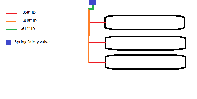
I am working on verifying a pressure relief system for NG cylinders with a Spring loaded safety device set to 5000 psi. I may be over thinking this but the jist of the problem I am having is that the piping leading to the safety valve is of 3 different sizes.

.358" ID for an equivalent of 1.5 feet off of 1 cylinder to a manifold that is .815" ID for equivalent of 10.5 feet to a reducing elbow that is .614" ID for an equivalent of 5.5 feet.

I am having trouble understanding the effects of the different piping size and what it would essentially do to the pressure drop from the cylinder to the safety device. My thought is to determine the combined volume, pressure drop and temperature of the inlet gas of the 3 smaller ID tubes. Use that as the starting pressure and temp for the manifold tube and calculate the pressure drop of that tube to the next reduction, and continue to the safety valve.

I attached a simple diagram of how the gas is traveling.
Safety_valve_diagram_jvon3s.png
 
Replies continue below

Recommended for you

What are the depressurization conditions? If you start with tanks at 5000 psig and set your relief at 5000 psig, you will not ever get any flow moving to the relief valve.

First you need to set the relief capacity that you need, apparently to keep all the the tanks at pressure lower than their allowable overpressure.

As an example (all numbers made up).

You need to know the allowable overpressure of the tank. If its 10% higher than allowable working pressure of 5000, that would be 5500 psig in the tank, You now have a differential pressure to drive flow.

So you set the relief at 5000 and you would get that 500 psi pressure differential when and if the tanks reached 5500 psig and you can now calculate the flow rates in your assumed pipe lengths and diameters. Initially assume that 1/3rd of the flow comes from each tank and they total Q1, your flow at the relief valve.

Knowing the total flow at the relief valve, take a guess at the amount of the flow rates in each pipe segment, such that they all sum to the Q1 value. Calculate the pressure drop in each pipe segment.

Now start at the relief valve pressure of 5000 psig and work towards the tanks, adding each pressure drop in each pipe segment. When you reach the tanks, you must have a value not greater than 5500 psig. If you get a value greater than 5500 psig, you have too much pressure drop and you must increase your pipe diameter(s), in one or more, or maybe even all of the pipe segments. If your value is less than 5500 psig, that's just perfectly fine, but maybe some of the pipe segments can have smaller diameters. Your choice if you want to try to make them smaller.

Just keep on adjusting diameters and adding pressure drops until you get a number for tank pressure less than 5500.

When you are happy with that number, you know the flow rate that your piping will do to allow you to keep your tanks at less than 5500 psig. That's your relief capacity.

Only one more thing to do. You must verify that your tanks will not exceed that relief capacity.
That depends on what's causing the overpressure.

If you are filling the tank battery with a compressor at 100 ft3/minute, and that flow rate is higher than your relief capacity, you have to reduce your vompressor flow, or increase your relief capacity to at least equal the compressors flow rate.

If you have a fire and it heats the tanks up to 400 degrees in 5 minutes, you must calculate a reduction of the amount of gas in the tanks that you will need to keep the pressure below 5500 psig at say 70F + 400 = 470°F. Once you know the volume reduction, you can assume you must discharge that volume through the relief valve in the 5minutes it takes to get hot. Your relief capacity must be higher than that fire case discharge flow rate.

Finally size your relief valve for the biggest flow rate of all your safety condition scenarios at whatever your set pressure turns out to be. There are often other limitations that I have not mentioned, backpressure limits, if your relief valve goes into other piping, or if it goes directly to atmosphere,

so ... That's just the basics on how to solve this type of problem.


--Einstein gave the same test to students every year. When asked why he would do something like that, "Because the answers had changed."
 
Thank you, that clarified it up a bit better than the CGA S-1.3 -2020 document I have been working with. They go about calculating it slightly different. I have all the necessary information for the valve and pressures, 3738 SCFM of valve and MAWP-5500 psi, with an assumed OP of %10 percent, I believe that is why the company set the Relief to 5ksi. Also according to CGA, it's stated that it shouldn't have more than a 3% pressure drop from the tube to the relief device, which was the issue I was having figuring out with the changing pipe sizes.

I'll look at it in the manner you described and give it a go. thank you!
 
There's a few ways to solve, whether you start with assumed pressure drops or flows and if you start at the tanks, or the valves, but they all eventually converge on the same answer.

Yes, sometimes there are total dP limits on the piping, pipe slope limits, drain towards the relief, etc, etc. and other "gotchas" to be aware of. Watch the compressibility factor. It will increase required capacity. At at those high pressures, the gas is not going to act like an ideal gas. As for system design conditions, rapid blow downs can make piping get pretty cold, so you may want to calculate final discharge temperatures for proper pipe material selection.

--Einstein gave the same test to students every year. When asked why he would do something like that, "Because the answers had changed."
 
As long as the cylinders are quite close to each other, the header is large enough that all the tanks will discharge equally so your flow calcs are really about the header and the green pipe.

But where is the pipe connection to something else using gas?

Show us the whole picture please.

Remember - More details = better answers
Also: If you get a response it's polite to respond to it.
 
This is just tank relief system. The other piping can be a separate exercise.
First let's get this bit right.

--Einstein gave the same test to students every year. When asked why he would do something like that, "Because the answers had changed."
 
I usually start at the end of the line and work backwards. You know the flow and can first assume it is split evenly among the three cylinders and that the relief valve pops at 5000 psi. Then perform pressure drop back to each cylinder. Pressure drop of any of the 3 paths cannot exceed 3% of set pressure or larger pipe sizes are needed.

Since 10% over pressure is used to size relief valve then the actual maximum pressure at relief valve inlet will be 5500 psig. At higher 5500 psig pressure at inlet of relief valve then smaller pressure drop will be present than when 5000 psig was present therefore using 5000 psig as starting point and working backwards is conservative worst case to calculate pressure drop by 3% rule.
 
Snickster, I didn't understand your 2nd paragraph.
And, if the relief flow is calculated as I suggested above, is not the pressure at the Inlet to the relief valve equal to the relief valve's set pressure?
If the vent is to atmosphere, the outlet pressure is 0 psig (15 psia)
dP across the valve = Set pressure -atm pressure.

Could you elaborate?

LittleInch. I think this is why I wanted to get this part right first.

This is apparently a closed system; relief flow is happening from tanks without any inflow into the tanks from other piping. My systems usually have a (nearly) constant pressure source, like when a compressor is filling the tanks while the relief valve is flowing. Here I just realized that, without that compressor, like the fire case, relief flow exits the tanks and the tank pressure is being reduced as that gas volume leaves the tanks. The reducing tank pressure will reduce the total pressure drop from tanks to valve, which in turn, reduces the relief flow rate. The tank pressure is not constant. Without calculating the actual rate of pressure drop and the tank pressure at all values of time from 0 to the end of the 5 minute heat up time, and while trying to keep the design of the relief system on the conservative side, let's make an assumption that simplifies the calculations. Let's calculate the pipe diameters using the lowest tank pressure, when the relief valve has finished flowing and all that fire gas volume has exited the tank. (Neglecting Z).


INITIAL CONDITIONS
Tank vol = 10,000 ft3 each = 30,000 ft3 total of all tanks
Initial tank condition is 5000psig at 70°F.
Initial gas volume is 30,000 ft3 at 5000 psig
Initial gas volume SCF = 30,000 x (5000+15)/15 = 10.03MM SCF

Find Molar quantity (1m of gas at stp = 379ft3)
Initial lb-moles = 10.03MM/379ft3/lb-mole = 26,464 lb-moles

HOT CONĎITIONS (Find P2)
Final tank condition is 470°F
P2 = P1 x V1 / T1 x T2 / V2
V1=V2
P2 = P1 / T1 x T2 = 5015 / (460+70) x (460+470) = 8800 psia

Check the molar quantity
m =P V /R/T
m= 8800psia x 30,000ft3 / 10.72 /930°R = 26464 lb-moles


VENTING OF GAS
Reducing the pressure to the relief valve set pressure
Requires Venting of gas, but how much?

What amount of gas at 470°F has a pressure equal to
Relief Set Pressure = 5000psig
P V = m RT
m=P V /R/T
m= 5015 x 30,000/R/(460+470)
R = 10.72
m = 161,774/R
final tanks contents = 15,199 moles


How much gas needs to be vented?
26,464-15199 = 11,350 lb-moles
11,350 m x 379ft3/m = 4,301,650 SCF
Whoa! That's a lot of flow in 5 minutes. My 5m heat time was too short.
Let's say it takes an hour to reach 480°F
So that vent flow rate now will be 4.3 MMSCFH

Now we decide what our final tank pressure should be when the vent closes. Can we say 5250 psia. We could go to 5500psig, but I want to see what happens if we don't use max., if we pick a lower pressure. So we would have a minimum dP on the relief piping of 5250-5000.= 250psi Remembering that the Max could be 5000 and the relief flow that much higher.
So, finally we arrive at a pipe design flow of 4.3 MM SCFH with a 250 psi pressure drop. Flowing Temperature of the gas is 470°F. Max pressure rating needed is 5500 psig.

So, now when that flow rate starts reducing, say at a tank pressure of say 5249, the pressure in the relief piping will start to build up again to current tank pressure and the relief will open and it will make a few sputters as flow slows down. Seems that the relief piping will see some pressure cycling as the flow eventually reduces to 0 and the final tank pressure reaches almost exactly equal to the relief valve setting.

I never really thought about the depressuring process at a level of detail before.
Interesting to see why the relief valve chatters as flow rate fillaly stops.
Is all that making sense?

--Einstein gave the same test to students every year. When asked why he would do something like that, "Because the answers had changed."
 
Mr 44,

Check this line....

Initial gas volume SCF = 30,000 x (5000+15)/15 = 10.03MM SCF

Eh? 30000 scf x pressure in psi equals even more SCF??
Too much sangria?

Remember - More details = better answers
Also: If you get a response it's polite to respond to it.
 
This is a simplification but should get you close enough to determine if the inlet DP for the relief is ok, which is what it sounds like the goal is: treat the three red branches as three resistances in parallel. Develop a flow resistance factor (K) for each segment, add the total equivalent resistance of the three parallel red branches to the others in series to get a total resistance factor. With a total equivalent K you can solve for DP using the rated flow of the relief valve.

K_tot = K_green + K_orange + 1/(1/K_red + 1/K_red + 1/K_red)
 
GBT, Yes, I was going for a Conservative simplification. I'm too lazy to break out the simulator today.

LittleInch,
Let's check it this way.

Tanks gas content At 5015 psia and 70°F
m = PV/R/T
m = 5015 x 30,000 / 10.72/ (460+70)
m = 26,480 lb-moles

Now we find SCF
26480 lb-moles x 379 ft3/lb-mole
10,035,920 SCF
10.03MM at 14.7 psia and 520°R

Check moles at stp 14.7 psia and 60°F with
m = PV/R/T
P=15 psia
V = 10.03 MMCF
T = (460+60) = 520°R
m = 14.7 x 10,035,920 CF / 10.72 /520
m = 26,465 lb-moles

26,465 lb-moles app = 26480 lb-moles
If I had used a more exact conversion of lb-moles to SCF of 378.785 instead of 379 SCF/lb-mole it would have been exactly equal.

So yes, I think 30,000 ft3 at 5000 psig and 70°F contains 10,035,920 SCF of gas.


--Einstein gave the same test to students every year. When asked why he would do something like that, "Because the answers had changed."
 
Thank you everyone for your input, i will go over the information that you have given me to help design my calculations. 1503 it does make sense as to why the valve starts to chatter. I am new to the engineering world and I am thankful for all your help. Just for clarification for everyone, these are ground storage units for NG, so they provide the supply for the most part. Therefore under fire conditions would be when the PRD is most likely going to be engaged.
 
I guessed right for a change.😀

--Einstein gave the same test to students every year. When asked why he would do something like that, "Because the answers had changed."
 
@1503-44 I meant the parallel K factors I described is a simplification. The way I read it OP is asking about pressure drop not relief sizing.
 
GBT, that is correct, basically to verify that the drop though the inlet side of the PRD was no more than 3% compared to the MAWP indicating lack of flow which could cause chatter or cause too much build up in the vessels under fire conditions where it can't relieve fast enough.
 
I figured that, since Engweld didn't seem to know how the pressure drop worked, he might need some help with determining the flow. I see now that Engweld said he was verifying valve size. Didn't notice that before. I thought he was designing the whole system. Anyway, now he can verify the whole system. And, if you do not know the flow capacity of the relief valve, ie if you have to size and specify the valve, you can't size the pipe. You must first have a method to determine the required minimum valve capacity. Then that becomes the minimum capacity of the Pipe. You also can't know the total K factor without eventually calculating and summing the individual pipe K factors anyway. If you determine total K, then you still have to eventually turn those into individual K values, then determine diameters from those. It usually makes more logical sense to beginners to work with diameters and calculate individual pressure drops then add them, rather than calculate total dP and then have to figure out the minimum diameters that you need to get that total dP. At least I think so. And I made the problem interesting enough to make it worth my time to solve it. I get bored with just adding up pipe factors. Sorry if I overworked the short solution.

Anyway ... Engweld, I hope you were able to follow all that.
If you have any more questions, now is a good time.

--Einstein gave the same test to students every year. When asked why he would do something like that, "Because the answers had changed."
 
Snickster, I didn't understand your 2nd paragraph.
And, if the relief flow is calculated as I suggested above, is not the pressure at the Inlet to the relief valve equal to the relief valve's set pressure?
If the vent is to atmosphere, the outlet pressure is 0 psig (15 psia)
dP across the valve = Set pressure -atm pressure.

Could you elaborate?


I am used to sizing a relief valve and piping as follows:

Set pressure is MAWP of vessel. Actual relieving pressure is 1.1 times the set pressure to allow for overpressure/accumulation.

Determine pressure drop from vessel to relief valve such that pressure drop does not exceed 3% of set pressure. At 5000 psi this would be 150 psi allowable pressure drop.

When the relief valve initially pops it will be at set pressure (5000 psig). Assuming the maximum design flowrate used to size the relief valve is being relieved, when the valve initially pops only 90% of flow will pass through the valve and 10% (and steadily decreasing amount) remainng in vessel that increases the pressure of the vessel until the pressure at the relief valve inlet reaches 5500 psig (not the pressure in the tank). However per API 520 if you stay below 3% pressure drop you can ignore the added pressure in the protected vessel due to the 3% or less drop.

Therefore if you calculate the 3% pressure drop based on an inlet pressure to the relief valve at 5000 psig, when the relief valve inlet pressure is 5500 psig then the pressure drop will be less than 3% since pressure loss decreases at higher pressures with a gas. So if you pass the 3% rule at lower pressure than at any higher pressure you will also pass.

Note that for a large vessel it will take some time for the pressure to reach maximum deisgn relieving pressure of 1.1 times set pressure (considering a 10% net flow remains in the tank and decreases as time goes on). Could be very long and it may not happen at all since the excess flow may go back to normal for some reason before the pressure actually gets up to 1.1 set pressure. So the valve will chatter in the meantime.
 
NG at 5000psig - should be using flanged piping, not compression tubing for line to PSV and other process piping.
What is your firecase scenario? Fire input at one cylinder only, or at all cylinders simultaneously ?
Fire at these cylinders is rather unlikely if there is no containment dike and there no instrumentation tubing impulse lines on each cylinder. What does your CGA say about the likelihood of fire in such an assembly?
 
Snickster, Yes, you are right. That is the recommended practice. Thanks.

--Einstein gave the same test to students every year. When asked why he would do something like that, "Because the answers had changed."
 
Status
Not open for further replies.

Part and Inventory Search

Sponsor