Continue to Site

Eng-Tips is the largest engineering community on the Internet

Intelligent Work Forums for Engineering Professionals

  • Congratulations KootK on being selected by the Eng-Tips community for having the most helpful posts in the forums last week. Way to Go!

Profile of a Surface 1

Status
Not open for further replies.

James Orlando

Mechanical
May 14, 2018
2
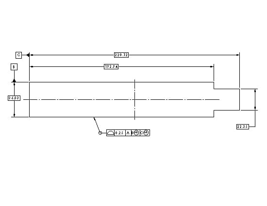
I'm hoping someone can help me answer the correct meaning of the Profile of a Surface call out is on this drawing. We have two individuals with differing opinions and I would like to understand the true intention.

The part has an overall dimension of 220.12. The side surface (B) has Profile of a Surface of 0.25 mm.

Does this mean that the overall dimension would be +/- 0.5 mm or +/- 0.25 mm?

Thank you in advance for the help.
 
 https://files.engineering.com/getfile.aspx?folder=a9556a9a-812a-49bc-b1db-69bd51363182&file=Profile_of_a_Surface.jpg
Replies continue below

Recommended for you

CH,

Can you provide a reference from Y14.5 that states (or illustrates) that directly toleranced dimensions can include dimensions "controlled by a FCF" ? I don't like to nit-pick on wording and terminology (well, actually, I do), but here is what Y14.5-2009 actually states in Section 2.2:

DIRECT TOLERANCING METHODS
(a) Limit Dimensioning. The high limit ...
(b) Plus and Minus Tolerancing. The dimension is ...
(c) Geometric Tolerances Directly Applied to Features. See sections 5 through 9.

I would say that (c) does not open the door to surfaces controlled by profile tolerances with basic dimensions becoming features of size. A geometric tolerance applied to a feature is not an example of a directly toleranced dimension. The geometric tolerance applies to the feature, not to the dimension. I would also say that basic dimensions are not controlled by the FCF. Basic dimensions are theoretically exact, with no tolerance. So the 220.12 and 36.83 width and height are not directly toleranced dimensions.

Regarding the self-referencing FCF, the effect of only half the profile tolerance being available only applies when the datum feature is a single planar surface. If the 4 features were part of B and C as you say, then the entire profile tolerance would be available. This is best illlustrated with a couple of sketches.

Evan Janeshewski

Axymetrix Quality Engineering Inc.
 
CH and All,

Here are a couple of slightly edited versions of the OP drawing, where the theoretically exact geometry is the same but the explicit indications are different. Would B and C be features of size in either of these cases?

B_and_C_on_Basic_Widths_l1ittd.png


B_and_C_on_Basic_Widths_ypl8ox.png


Evan Janeshewski

Axymetrix Quality Engineering Inc.
 
axym said:
1. DIRECT TOLERANCING METHODS
...
(c) Geometric Tolerances Directly Applied to Features.

...

2. A geometric tolerance applied to a feature is not an example of a directly toleranced dimension

Could you be so kind to pick one, because they contradict each other?

As to your pictures, then no, they are not features of size (don't forget to remove center lines).
What difference does it make?

"For every expert there is an equal and opposite expert"
Arthur C. Clarke Profiles of the future

 
axym,

Someone has pointed out that this all would be simpler if the profile had been based on datum feature[ ]A, only. The other datum features do not matter unless there are other features on this thing not shown on the sketch.

Your first sketch is just a repeat of the OP's sketch. Datums[ ]B and[ ]C are based on features that vary in size. The fixture that picks up datum feature[ ]B must account for the size variation, and it must locate the part left/right as well as in rotation. I am glad this is not my problem. If this were my part perhaps with holes in it, I would use the holes as my datums features[ ]B and[ ]C.

TESTINGTESTING_wdofn3.jpg


Above, I have modified the OP's sketch. I have made the proportions more manageable for inspection, and I have added conditions to the features of size. You can now build an inspection fixture, although, unfortunately, the part no longer works.[ ][smile]

My biggest problem is not that the datum features are self referencing. I would strongly prefer an FOS datum feature to be very much more accurate than the features I must inspect. If datum feature[ ]B were a dowel hole and feature[ ]C were a slot, both within [±]0.01mm, fixturing and inspecting this part would be easy.

--
JHG
 
Back to 3DDave's situation of a self-referencing hole... Here's why it's STILL different from the OP example on this thread:
How is datum B created? From the AME of the hole.
What is position checking? The axis of the AME of the hole.
Thus, it's not only confusing, but meaningless.

In the OP situation, How is the datum created? From the AME of the width.
What is profile checking? The actual surface(s). Not the AME.

So what might be called self-referencing is actually checking the form of the surface to a datum derived from the AME. Position doesn't do that.


John-Paul Belanger
Certified Sr. GD&T Professional
Geometric Learning Systems
 
The generally accepted result is that only half of the profile tolerance zone is available for the datum feature.

Evan, I don't know if that's true for the profile example at hand, because the datum is created from the centerplane as derived from the high points of the two sides (AME). For an earlier thread that CH brought into this discussion, I would agree with your statement, because that was using surface-derived datums. But here, you could have a datum CP derived from the AME, and then dial back out according to the prescribed basic dimension, and still have some hight points or low points within the full range of the profile tolerance.

John-Paul Belanger
Certified Sr. GD&T Professional
Geometric Learning Systems
 
JP,

How do you know where this nominal profile is supposed to be? From the Center of itself.

Locating a hole from the location of a hole is not meaningless, it has a meaning. It's just not useful, and neither is referring the location of a profile zone from the feature that defines the location of the profile zone.
 
axym,

Per ASME Y14.5-2009, a regular feature of size requires a directly toleranced dimension. I agree that OP's image contains none of these. However, an irregular feature of size only requires a directly toleranced feature. Surely you'd agree that the profile tolerance is directly applied to the feature.

For what it's worth, we had essentially the same discussion in thread1103-404621. You seemed convinced at the time.


Belanger,

Regarding 3DDaves's example: Datum B is based on the RAME, but the position tolerance applies to the axis of the UAME. I'm not saying it would be terribly useful on a drawing, but it would generally have a non-zero actual value.

Oddly enough, this idea was actually useful for me recently. As a way to check whether some inspection software was correctly handling a datum feature reference, I programmed it to check position on the datum feature. This was a 2D measurement, so the reported value should have been exactly zero. Unfortunately it wasn't.


pylfrm
 
pylfrm -- that's true; the position comes from UAME and the datum is RAME. And to be clear, I'm not defending confusing practices! I'm going through all this to try and differentiate all the nuances of these examples (all of which are confusing).

John-Paul Belanger
Certified Sr. GD&T Professional
Geometric Learning Systems
 
CH,

#1 is a quote from Y14.5-2009, that says that a geometric tolerance directly applied to a feature is an example of a direct tolerancing method.

#2 is my opinion, that #1 does not mean that a geometric tolerance directly applied to a feature is an example of a directly toleranced dimension.

drawoh,

In the first alternative drawing, I moved the basic dimensions so that they are no longer in line with the datum feature labels. This should mean that each datum feature is a single planar surface.

J-P,

I think that we're generally in agreement on the effects of the self-referencing profile tolerance and the generally accepted result. But this isn't obvious from the one partial statement that you quoted! The sentence actually started with "I believe that the case of the single planar datum feature has been addressed". Also, in the next post I restated that the halving effect only applies to single planar datum features, and for width features the entire tolerance is available. So I think that we're on the same page with that.

Regarding the self-referencing secondary datum feature hole, I would say that this is somewhat misleading but not meaningless. Pylfrm is correct that the datum is established using a RAME but the position zone controls the axis of the UAME. The end result is that the position tolerance controls the orientation of the hole with respect to the datum A plane. I would recommend that perpendicularity be specified in this case, but the position tolerance still has meaning.

pylfrm,

You're correct about the irregular feature of size, and the directly toleranced feature. I read through the earlier thread you referenced and it's coming back to me now. We beat this to death two years ago. I put forth the same arguments that I did in this thread, but then pmarc correctly pointed out that Fig. 4-33 opens the door to centerplane datums defined on features with profile tolerances and basic width dimensions.

As I said in the other thread, I've never really been a fan of the "irregular features of size" development. The idea of using regular (cylindrical or parallel-plane) simulators to establish datums on quasi-regular discontinuous groups of surfaces is fine. But it seems that this could have been addressed using some type of datum target application, instead of creating a confusing variant of size.


Evan Janeshewski

Axymetrix Quality Engineering Inc.
 
May I have a quick question for pmarc:

pmarc said:
......because half of the tolerance zone width is unsable as it lies inside the material of datum feature A-B simulator, and the datum A-B is established by the high points of surfaces A and B simultenously.

This concept has not been explicitly pictured and described in the Y14.5-2009, but most likely will be covered in the future version of the Y14.5

My note: Quote from the related thread.

The question: could you please indicate the paragraph, picture or page number from the draft ? I cannot find it and I am still searching it.

Also in Fig 7-40 (draft)-page 162 why datum feature B is the inside surface, but in its applicable isometric view is the outside (or at least seems to be the outside)? Most likely mistake, isn't it?


greenimi,
In that discussion I was thinking of fig. 11-21 and para. 11.4.3.1.

As for fig. 7-40 in the draft, you are right, this is a mistake - one of zillions they made at that point.
 
axym said:
#1 is a quote from Y14.5-2009, that says that a geometric tolerance directly applied to a feature is an example of a direct tolerancing method.

#2 is my opinion, that #1 does not mean that a geometric tolerance directly applied to a feature is an example of a directly toleranced dimension.

Evan,
Would you mind, just for a few seconds, to explain the above quote in more details. I am trying to learn peoples perspectives and viewpoints, but sometimes my English language fails me.
Thank you Evan.


Kedu,

This quote is difficult to explain and doesn't make sense on its own. It's a piece from a back-and-forth discussion between myself and CH within this thread, where we were going over the meaning of tiny differences in wording. It probably looks like my English language failed me in this case ;^).

I won't try to explain the quote directly - it's too far removed from the original meaning, which was in my post on May 15 at 18:48. The point I was trying to make was that pairs of planar surfaces controlled by an all-around profile tolerance with basic dimensions do not meet the criteria for regular features of size, by the definitions in Y14.5-2009:
-The definition for Regular Feature of Size in section 1.3.32.1 requires the presence of a "directly toleranced dimension"
-The definition for Direct Tolerancing Methods in section 2.2 includes "Geometric Tolerances Directly Applied to Features".

So pairs of planar surfaces controlled by an all-around profile tolerance with basic dimensions would be an example of a geometric tolerance directly applied to a feature, and thus an example of a Direct Tolerancing Method. But the all-around profile tolerance does not involve directly toleranced dimensions, and thus the pairs of planar surfaces are not regular features of size.

Evan Janeshewski

Axymetrix Quality Engineering Inc.
 
Well said, Evan. And that brings up a tangential question about "directly toleranced dimension" ... If a dimension given on a print (a simple one such as diameter, length, or width) is not followed immediately by a ± type of tolerance, and it is not reference nor basic, but instead it appeals to a general tolerance in the notes, does that qualify as directly toleranced?

John-Paul Belanger
Certified Sr. GD&T Professional
Geometric Learning Systems
 
I didn't say you're wrong. I'm showing how words can be confusing even when the standards committee thinks it's clear.
Wouldn't it be easy to say that a "general tolerance" and a "direct tolerance" are opposite (in terms of their adjectives)?

John-Paul Belanger
Certified Sr. GD&T Professional
Geometric Learning Systems
 
J-P,

I would say that a dimension governed by a general +/- tolerance would qualify as a directly toleranced dimension. If it didn't, then it would not be considered a feature of size and hence not subject to Rule #1. It would be very confusing if things worked that way.

I agree that the words are confusing and also inconsistent. The meaning of the term "direct" in this context relates to the application of the tolerance to the dimension, and not to the physical location of the tolerance on the drawing. Even an implied 90 degree angle, that is not specified, is an example of a directly toleranced dimension. Sigh.

This brings up a question - what would be an example of an indirectly toleranced dimension? Does the word "directly" mean anything? Or could the term just be "toleranced dimension" ?

Evan Janeshewski

Axymetrix Quality Engineering Inc.
 
I agree with you Evan (and also with greenimi). Again, I was just pointing out the possibility of confusion given the qualifier "directly."

An indirectly toleranced dimension might be one that is a stack-up result from a chain of other dimensions. But then the "dimension" in question wouldn't be given anyway (unless as a reference dimension)! Ugh, semantics...

John-Paul Belanger
Certified Sr. GD&T Professional
Geometric Learning Systems
 
ASME Y14.5-2009 para. 1.4(a) said:
Each dimension shall have a tolerance, except for those dimensions specifically identified as reference, maximum, minimum, or stock (commercial stock size). The tolerance may be applied directly to the dimension (or indirectly in the case of basic dimensions), indicated by a general note, or located in a supplementary block of the drawing format. See ASME Y14.1 and ASME Y14.1M.

I think this is a rather unfortunate paragraph, but it does provide answers to some of the recent questions here. Whether or not those answers make sense is another question.


pylfrm
 
Status
Not open for further replies.

Part and Inventory Search

Sponsor