Continue to Site

Eng-Tips is the largest engineering community on the Internet

Intelligent Work Forums for Engineering Professionals

  • Congratulations cowski on being selected by the Eng-Tips community for having the most helpful posts in the forums last week. Way to Go!

Profile of a Tapered Insert 1

Status
Not open for further replies.

ATC350X

Mechanical
Dec 19, 2022
9
Greetings Everyone,

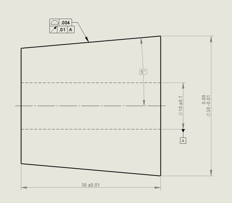
New to the forums and hoping some of you can shed some light on calling out a profile tolerance on a tapered insert. I have attached a picture of a simplified insert that I commonly work with at my company. From what I have been told, the large diameter dimension, length and the angle of the taper are what are important for establishing the part since the insert is placed inside of a tapered bore along with other inserts. The ID is re-finished when all inserts are in place. Therefore, during manufacturing of the insert, it is not crucial to have the ID axis and the cone axis perfectly concentric. To try and show this while holding the taper, the drawings are formatted with the shown GD&T. The way it is supposed to read is "the angle of the taper needs to be held essentially perfect but the entire cone can move radially a little bit about the ID axis". Being newer with GD&T I am not 100% sure what is shown on the drawings is correct and/or makes sense. I have found many examples of profile of a conical surface but nothing quite like this. The only hardcopy standards I have available is ANSI Y14.5M - 1982 (a bit out of date, I know). In this standard I looked at Figures 190 and 191. If I was dimensioning this based on examples, I would simply omit the circular runout tolerance and move the Datum A reference up to the profile tolerance. However, this means the profile in relation to the ID axis will be held extremely tight when it really doesn't have to be. Can anyone provide any input on whether or not the layout of this tolerancing is correct or possibly a better way to do it? I've looked at composite profile and MSS profiling but not sure if that is the way to go. Of course, if further explanation is needed, I can provide that since I am sure I haven't quite explained things clearly.

Thanks in Advance.
 
 https://files.engineering.com/getfile.aspx?folder=18470871-b7e5-41a8-9872-112819bae0cd&file=Insert.JPG
Replies continue below

Recommended for you

Insert_azzy0s.jpg
 
It's typical/described as using the full included angle to specify the taper.

If you used the conical surface as a datum feature the hole could have a position tolerance relative to it.

You could also control perpendicularity of the end surfaces to the conical surface.
 
Thank you 3DDave for the input. I had thought about using the cone as a datum like you mention but was not sure if that was common practice or if it caused any problems with inspection. I also forgot to mention and show on my picture that we do specify a total runout tolerance of 0.01 on each end of the cone in reference to Datum A which would control the perpendicularity you mention. As a company, the end goal is to cleanup some of our drawings to make the gd&t understandable, obtainable and inspectable. What I had shown in my picture is the first attempt at doing so; what was in place prior was very confusing.
 
"caused problems" = go talk to your inspectors. Unless the part turns during operation runout isn't the best choice. What's not common practice is to choose a feature as a datum feature that will be machined away at the next operation.
 
I would agree. In regard to my original picture, would the current gd&t callout even work? In an effort to support the suggestion of the cone datum with positional tolerance to my department, I would like to understand why it would or wouldn't work. I personally don't believe it is the best way to describe intent, but to convince everyone else will take reference to a standard or example.
 
ATC350X,
Putting the discussion about which of the two features, the cone or the hole, should be the datum feature aside, and knowing that both ends of the cone are controlled with a total runout tolerance relative to datum axist A, I would say that the current scheme is acceptable.

The profile tolerance, the basic angle and the toleranced diameter at the larger end closely correspond to what Figure 190 in Y14.5M-1982 shows and the circular runout tolerance is just a different way of controlling location of the cone relative to the datum axis than the profile with datum A shown in Figure 191.

Side note: To give you a bigger picture, I think you should also know that there has been a lot of controversy in the GD&T world around the schemes shown in Figures 190 and 191, which is basically due the fact that profile tolerance is combined with a directly toleranced diameter in both figures. But while the rules in Y14.5 standard evolved since 1982 in a way that the latest and greatest figure corresponding to Figure 191 does not have a directly toleranced diameter anymore, Figure 190 has basically stayed unchanged.
 
Take a look at this figure from the 2018 edition of the standard.
cone_s1ydoe.png
 
Wuzhee,
If you could also attach figure 11-19, it would prove what I wrote in the side note of my previous reply.
 
ATC350X,

When ever you produce a fabrication drawing, ask yourself how somebody is going to inspect it.

In your case, you have a very accurately toleranced dimension placed across a part with sharp corners. In the real world, the corners will not be sharp. If you need an accurate diameter, you need to flatten the face out, like Wuzhee's figure above.

--
JHG
 
Wuzhee, I do not see the figure you mention. It seems drawoh was able to view it but maybe I am not looking in the right spot.
 
I think it's common practice to determine control dimensions on conical and irregular profile revolutions. Just like Fig 11-20 from the standard. That's what we do with our odd shaped parts.

From the standard:
fig_11_19_ualgbs.png

In Fig 11-19 the profile only refines form.
In Fig 11-20 profile referenced by datums refines form, orientation, location. Size is controlled by the dynamic symbol in the lower bracket of MSSFCF.

Attached the fig 11-20

 
Copy and paste the URL of the link you get when uploading and then upload another one and copy and paste that URL - repeat as often as desired (but not too crazy about the number.)
 
Thank you all for the replies. In response to a couple:

drawoh, I understand your point about the sharp corner. However, for this part the design doesn't allow for a flat section. The entire taper must be in contact with the mating tapered bore. Even if the corner isn't perfectly sharp (although the taper and ends are ground to size which leaves it quite sharp) we can use the theoretical sharp corner during inspection.

Wuzhee, thank you for the figures. In Fig 11-20, what is the meaning of the triangle symbol? This is obviously not shown in Fig 190 of the 1982 standard I have available, and I can't say I have ever run into it before. I am pretty sure since it is a MSSFCF, it can't be omitted since then the lower line would override the top. What I am also noticing is that since the control frame is MSS, the way tolerance zone is setup is two zones offset from the theoretical perfect surface. I have attached a document with screenshots of what I believe were prior standard examples (many of which I found on this forum) that show composite callouts. In those cases, the top line goes with the diameter dimension and then the bottom line outlines the profile. Again, the triangle is present. Just trying to wrap my head around how using composite/MSS frames and the triangle yields the slightly different results.
 
 https://files.engineering.com/getfile.aspx?folder=ff4ec75a-4072-4d27-ba9a-8ebb9140b466&file=Profile_of_a_Cone.docx
In Fig 11-20 the triangle modifier indicates to ignore the "size" tolerance (a cone hasn't got one, but that's another problem) and just make it uniformly cone-like within the smaller tolerance zone.

As a practical application it's not required for this - by keeping the taper a basic value the only thing that really changes if more or less material is removed from the part is where the cone's vertex is along the axis.

By calling out datum B, the location of the vertex would otherwise be fixed, which is the case for the upper FCF. So they added the triangle.

They could have skipped needing the triangle by dropping the datum B reference, but it's a new toy so they had to play with it as much as possible.

About "MSSFCF." I can't say no one uses it, but it took a search to find what it meant - and I started with the 1973 version. I don't even know why they bothered creating that term.
 
ATC350X

Back to your original drawing, I would omit the runout because it's ambiguous with the size dimension. Having a Ø30-0,01 dimension also means a 0,01 mm of circularity because of Rule #1. And runout is circularity+concentricity. So a 0,01 runout wouldn't help at all.


ATC350X said:
drawoh, I understand your point about the sharp corner. However, for this part the design doesn't allow for a flat section. The entire taper must be in contact with the mating tapered bore. Even if the corner isn't perfectly sharp (although the taper and ends are ground to size which leaves it quite sharp) we can use the theoretical sharp corner during inspection.

Be careful applying toleranced dimensions across sharp corners. These will be rounded off in fabrication unless you clearly specify otherwise. If you need an accurate face, you need to apply geometric tolerances like profile and runout to the tapered face.

--
JHG
 
Wuzhee,

Wouldn't the runout allow the whole cone feature to be offset in reference to Datum A providing the form of the diameter varied less than 0.01? I guess I view it as sort of a bonus. The closer to a perfect circle the diameter is, it would be allowed to be offset slightly. Not saying it is the best way to tolerance the part, but I think it could work.
 
Status
Not open for further replies.

Part and Inventory Search

Sponsor