Eng-Tips is the largest engineering community on the Internet

Intelligent Work Forums for Engineering Professionals

profile on trimmed edge 8

Status
Not open for further replies.

DGN1975

Mechanical
Dec 18, 2019
7
0
0
US
does anyone have idea or references how to profile tolerance a complex trimmed edge on say a vac formed part? I don't really see any good examples in the standard to other places. Would it make sense to just point to the trimmed edge with a 'ALL OVER' profile tolerance with a note below that states "trimmed edge". using "all around" wouldn't work to me as it is controlled only in the view its shown in and a trimmed edge would go all around in 3d.
 
 https://files.engineering.com/getfile.aspx?folder=a48fcf2e-7932-4edf-b9cb-17b5e0eec599&file=vac-form-sample.JPG
Replies continue below

Recommended for you

You made a poor recommendation to every reader of this thread. It required correcting. You keep making it worse.

"the profile defined by" - clearly depends on the definition of profile. Invalid profile = invalid true profile.

It doesn't say - a surface that follows the border of another surface but runs off in some direction.

The surface being controlled has two outlines in each view. Y14.5 surface profile doesn't control based on two outlines.

The Y14.41 faction is trying to expand profile into a universal surface offset, but the Y14.5 group did not adopt that.

Perhaps if you stop defending the bad decisions there would be a little more pressure for better ones to be made.
 
3D,
You've been trying to convince the OP and every reader of this thread that a severe problem exists and that this problem prevents them from doing what needs to be done for their job. You've been doing this while applying a very narrow and faulty interpretation of the Y14.5 standard, and without offering any alternative.

You've been ignoring some parts of the definitions and emphasizing other parts which are irrelevant to the case being discussed.

From your own Y14.5 quotes from the standard which you brought above:
"PROFILE:...,a shape made up of one or more features,..." - there is no requirement for the shape to be fully described by a single 2D outline.

"A model or a drawing view is created to show the true profile" - as I said this this is doable. Even when no model is provided as part of the product definition and one view is not sufficient to fully dimension the surface - there is no restriction from creating additional sections, auxiliary views, etc.

I hope this settles the issue as there is really not much to add or argue over here - sorry if you find again a "failure to inform" - but all the necessary information has been provided and repeated by now.
 
It's an accurate interpretation of a faulty standard. Y14.41 is the only alternative, offered by the MBD faction and, ironically, by you. You have a blind spot, like the one in your retinas, that you fill in when there is no information.

I'm pointing out the error that you keep making.

Find an example from Section 11 that does exactly what you claim. All examples are of 2D projected curves, either linear or the silhouette of a surface of revolution, except in the case of "ALL OVER."

The Y14.5 Profile tolerance subcommittee agrees with my interpretation.

Applying the part of the definition supporting "ALL OVER" to any other case is your flawed interpretation.
 
Since when the lack of an example figure in the standard, let alone within a single section (while even present in another section), disqualifies a tolerancing practice?
At least until your idea to turn the standard into a picture book is realized, that is not the case.

Your interpretation is obviously faulty.
The flawed thought process and lack of attention is sticking out already in your first post in this thread (30 Sep 23 04:21), where you brought a quote beginning with:
"Profile of a surface may be applied to parts of any shape, including..."
Which was immediately proceeded with your statement:
"Your case does not meet any of the allowed applications."
How can a feature or a group of features not belong in a category that includes "any shape"? The "allowed applications" you were referring to are clearly just a partial list of what is included.

Besides, a model is not just a Y14.41 thing, so "Y14.41 is the only alternative" doesn't really make sense either. Y14.5 itself mentions and acknowledges models as part of its own product definition standardization content. Read the introduction to the Scope section:
"This Standard establishes symbols, rules, definitions, requirements, defaults, and recommended practices for stating and interpreting dimensioning, tolerancing, and
related requirements for use on engineering drawings, models defined in digital data files, and related documents"
.
The reference to Y14.41 is for "Additional" definitions related to MBD - but models are not separate from what Y14.5 covers.
 
Y14.41 is required to link the drawing requirements to the use of profile to individual surfaces that are not 2D projections or applied ALL OVER.

"Profile of a surface may be applied to parts of any shape," is for "ALL OVER." Note the critical word "part" and not "feature."

 
Y14.5 said:
Profile of a surface may be
applied to parts of any shape, including parts that have a constant cross section as in Figure 11-6, parts that have a surface of revolution as in Figure 11-19, and parts that have a profile tolerance applied all over as in Figure 11-9 (here they mean 11-10).
Obviously, "applied to parts of any shape" is not only for "all over" since "all over" is just the third example out of 3 specific profile application examples provided, and there was no intent to exhaust all possible cases of unique geometries.

3D said:
Y14.41 is required to link the drawing requirements to the use of profile to individual surfaces that are not 2D projections or applied ALL OVER.
Not necessarily. I already told you at least twice how it can be done without a model and therefore without referencing Y14.41.
 
"parts that have a constant cross section as in Figure 11-6, parts that have a surface of revolution"

Neither of those cases applies to the OP problem. Both are 2D projections as it has been since 1960.

Look at 1994 6.5 and then look at the intentional changes as listed in NONMANDATORY APPENDIX A PRINCIPAL CHANGES AND IMPROVEMENTS. You will not find support for your position.

Unless you have 2D constant cross sections or have a surface of revolution you cannot use profile of surface the way you want.

The definitions subcommittee screwed up and did not represent what the Profile Tolerance committee made clear. It isn't a Dan Brown novel of hidden meanings for only the most attuned conspiracy breaker to find clues from the Illuminati - every aspect should be obvious from the section text and examples and based on prior work except as clearly noted. It's not "take one word here, this phrase from the middle of a figure" and add in deeply pondering the alternate worlds theory.

The intentional 2009 changes:

A.10.1 Location of Tolerances of Profile Section
A.10.2 Unequally Disposed Profile Symbol
A.10.3 All-Over Application of Profile
A-10.4 Application of a Non-Uniform Tolerance Zone

The 2018 intentional changes:

A-13.1 Section Renumbered
A-13.2 Unequally Disposed Profile Specification
A-13.3 Profile All Over
A-13.4 Profile on a Nonsize Datum Feature
A-13.5 Orientation of Line Element Using Profile

Missing from that list is removing the 2D limitation except for ALL OVER.

The OP problem cannot be solved with Y14.5 and sections and views. It requires a note to describe the acceptance criteria or the use of Y14.41.
 
3D said:
"parts that have a constant cross section as in Figure 11-6, parts that have a surface of revolution"

Neither of those cases applies to the OP problem.
I agree. As I said, they are just examples. The question is - why do you keep bringing them up when they are clearly irrelevant? Again - these two and all over are not the only allowed cases - that's why it says "any shape".

3D said:
Unless you have 2D constant cross sections or have a surface of revolution you cannot use profile of surface the way you want.
There is no support for that. The lack of an example in the profile section doesn't prove this.

3D said:
Missing from that list is removing the 2D limitation except for ALL OVER.
Appendixes aside, as a fact, ever since the 2009 version, the body of the standard no longer defines profile as "the outline of an object in a given plane (two-dimensional figure)" (Y14.5M-1994, 6.5). And the body of the text has "a tiny bit" more weight than the changes' appendix.

I can correct and complete the figure you dislike from the datums section, without conflict with any current Y14.5 definition or rule:

image001_tplkgm.png


Profile definition (3.49): "...a shape made up of one or more features..."
- check.

True Profile (3.68): "the profile defined by basic radii, basic angular dimensions, basic coordinate dimensions, basic dimension of size..."
-check.

Profile (11.2): " A digital data
file or an appropriate view on a drawing shall define the true profile. "

- check:
An appropriate view was provided. Additional views for fully dimensioning the true profile are not forbidden. A digital data file is not a necessity.

Profile of a Surface (11.2.1.1): 
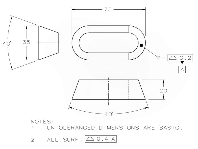
"Profile of a surface may be applied to parts of any shape" - no problem.

As I already mentioned, this example is a simplification of the OP's problem that has the same "issue" which he was concerned about - a peripheral surface surrounding the part which is not normal to the plane of the view projection or any other plane. Nothing to be worried about. Solvable with the all around symbol, and some additional views for full dimensioning and a lot of effort if a model is not provided (unlikely).
 
The error was made in 2009 to add "ALL OVER." There is no support for the change as a purposeful one as they fumbled the definition to do so. They added no example besides for "ALL OVER" indicating no intent and specifically did not add such descriptions as they did for profile of line.

Taking clues like a Dan Brown novel doesn't prove anything.

Your fix is even worse. It does not resolve to a point and proves you clearly have no business in GD&T.
 
You can guess all you want about what the intent was, the definition is what it is, and it supports that all possible types of geometries can be profile-controlled.

Why would I care that it "does not resolve to a point"? It matches the so-called "Complex" ("type g") feature category shown in the 7-3 table, and even if the specific proportions I made up do not allow the extrapolation of the surface to converge into a single point, that feature can still be used to constrain 6 degrees of freedom and establish 3 orthogonal planes and a reference origin for tolerance zones. It can be done in multiple ways too. The fact that you are looking for some specific datum point as the key to a solution only underlines your poor understanding of this subject and indicates that your experience doesn't go much beyond simple textbook / Y14.5 standard / training material examples. Good luck with learning.
 
You should care because that is what the diagram for what it controls shows. As I indicated, you don't even understand the error and made up an unrelated example that is not supported by the Profile subcommittee and the work they produced for their section.

The committee has accepted changes I submitted. You have never contributed. Good luck with learning beyond the picture book copy/paste.
 
"You should care because that is what the diagram for what it controls shows"

The diagram shows the datum which is derived and the degrees of freedom being constrained. The datum is shown as axis, point, and center plane. Another source, closely affiliated with the committee, offers a slightly different version of this figure, and skips the axis and the point. Instead, they directly provide 3 mutually perpendicular planes resolving from this geometry. Had you understood why, you would not think that the specific convergence to a point as shown in the standard is what really matters.

Seems like the picture book and copy/paste is your comfort zone after all.

As I already showed - the profile section has nothing against applying profile to any shape of a surface or surfaces.
 
There are an infinite number of things the standard does not deny but those are imaginary.

It is intended to show what is allowed.

Your other source matters not at all - the figure in the standard is incorrect and your fix makes a worse stab at it. There are infinite possible figures but the case is the shape shown does not match the constraints shown.
 
"It is intended to show what is allowed"
That is correct, but contrary to what you've been arguing, it doesn't mean that what is not shown is disallowed. In the context of the figures in the profile section:

Y14.5 about figures said:
The absence of figure(s) has no bearing on the applicability of the stated requirements
or practice. To comply with the requirements of this Standard, actual data sets shall meet the content requirements set forth in the text.

"the case is the shape shown does not match the constraints shown" - a statement you can't support.
 
I'm not going to teach constructive geometry to you without collecting an eye-watering fee. I can support it, and have previously. You should recall when I did.

I expect you never got a pencil and paper and a straight edge to create a 3rd view or auxillary view from the first two; frankly, it shows.
 
To sum things up, you have contributed nothing in this thread other than unsupported claims, distractions from the topic, and accusations. You must be proud.
 
B, Google "how to create projected views by hand"


Start with the isometric for (g) in Figure 7-3.

Thanks Wuzhee for the distraction. Any bets on if B will find the Illuminti treasure map hidden in the standard? No comment on the merits or the OP problem? Great collection of cartoons.
 
Status
Not open for further replies.
Back
Top