Eng-Tips is the largest engineering community on the Internet

Intelligent Work Forums for Engineering Professionals

profile on trimmed edge 8

Status
Not open for further replies.

DGN1975

Mechanical
Dec 18, 2019
7
0
0
US
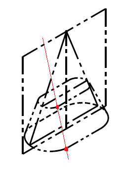
does anyone have idea or references how to profile tolerance a complex trimmed edge on say a vac formed part? I don't really see any good examples in the standard to other places. Would it make sense to just point to the trimmed edge with a 'ALL OVER' profile tolerance with a note below that states "trimmed edge". using "all around" wouldn't work to me as it is controlled only in the view its shown in and a trimmed edge would go all around in 3d.
 
 https://files.engineering.com/getfile.aspx?folder=a48fcf2e-7932-4edf-b9cb-17b5e0eec599&file=vac-form-sample.JPG
Replies continue below

Recommended for you

DGN1975,
If they removed the all around symbol by intent, I think it is because in this case the peripheral shape is an oval or something alike (with a varying cross section because of how that surface tapers as a result of staying normal to the bent plate faces). So unlike an oblong-based shape which you could clearly dissect to flat portions and rounds tangent to them and consider it as a collection of surfaces connecting together, the oval-based shape can be considered a single surface which is inseparable. Therefore, possibly when revising to the 2018 edition, someone thought the all around symbol, which is a grouping method intended to create a pattern from different surfaces (tangent or not) that form a closed shape, is inappropriate in that figure.

I see no indication in the standard that the considered surfaces must be exactly perpendicular to the plane of the view. I would say that as long as you can depict the peripheral surfaces closing a shape in the view (even with use of hidden lines to indicate slanted condition in places where the true shape of the surface is not visible), an all around symbol can be used in that view.
 
B,

You think because that is what I wrote, but maybe you never heard of "discontinuity" before.

“All Around” Symbol
For orthographic views, the symbolic means of indicating that a profile tolerance or other specification applies to surfaces all around a feature or group of features,

By that it no longer matters and the change made no difference or maybe you'll argue that it does, because it applies to "surfaces" and not surface, so discontinuities is back.

Is it marking the feature or the surfaces?
 
3D,
I'm not sure what you try to say by "You think because that is what I wrote, but maybe you never heard of "discontinuity" before".

What I can say is that contrary to what you indicated in your reply to the OP (which I read only now) the presence of sharp discontinuities is not the driving factor for the use of the all around symbol.

All around is listed as a grouping method in the definition of "Pattern".
 
3D said:
They show a trimetric that matches my interpretation

False. In a trimetric that would match your interpretation of a peripheral shape converging into a single point, the line connecting the two tangency points would end at the apex point where the axis originates:

7-3_g_pp3z8e.png


3D said:
The trimetric shows what the trimetric shows is the least informed place you have gotten to so far.

The least informed place is where you said "Occam's razor, adapted - the simpler geometry is the right one", assuming a shape that would work as you imagine is the simpler one. Try modeling the geometry that you think is the correct interpretation, then model what the standard shows or my version of the shape.
 
That cannot be - the profile is not all around for 7-3(g) so the cones cannot be separate.

As I wrote, the single surface is aligned with the point or else it would be two or more features. If so it would require "ALL AROUND" so I believe the text and the interpretation and they need to repair the figure.
 
B said:
No, and that was my explanation for the possible reason of removing the symbol in 2018. Get it now?

There is a saying that a blind squirrel will find a nut once in a while, and today you did.
 
As I said in my post where I first brought up the example (30 Sep 23 05:20):

In my opinion they should have included the all around symbol in this case as the intended true profile is made of a flat taper and two conical rounds grouped together. So it does have an oversight, but the principle is clear.

Both the trimetric and the orthographic views indicate a different scenario than what you assume the intent to be.

The text says nothing about converging into a single point.

No additional insights about the original topic - the applicability of profile of a surface to that shape? Try a better distraction next time.
 
It is applicable per Y14.41 as the drawing note should say.

The derivation and the FCF shows the intention; to converge to a single point.
 
There is no conflict between the "axis, point, center plane" for a datum and the shape shown in the figure, at the orthographic and trimetric views.

As I already explained at 4 Oct 23 19:46 there is:

a bisecting plane based on the flat taper and two lines created from the intersection of that plane with the semi-cones. The two lines meet at a point from which an axis that lies on the plane and bisects the angle between the two lines originates.
 
"As I already explained" That is not explanation - it is just your opinion on an unrelated geometry.

Your bisecting plane is generated by passing through the intersection of the faces, faces that are not aligned with the point. A scribble.

Example (g) does not show that intersection. It shows a single point. It does not require ALL AROUND. The intention is clear and the graphic is flawed.
 
"Example (g) does not show that intersection. It shows a single point"

It doesn't attempt to show the extension of the flat faces meeting at that point, either. Likely because it was never intended for them to meet there.

The lack of the all around symbol in that figure is the oversight.

You have nothing to base your interpretation on.
 
Which is more likely - a standard dedicated to symbols making that error in symbols or a bad model?

The same committee corrected one error in profile and didn't look at the other use?

The expected result shows the intent; that is the basis. The views and model do not live up to it.

Without that intersection of the flat surfaces one cannot locate or orient the midplane.
 
The "expected result" is only expected by you. You expect the committee to mean what you want and not what is indicated. Unfortunately, they forgot to ask you what they should mean.

There is an intersection between the flat faces, nobody said there isn't. It doesn't need to be at the datum point shown. The faces are used to derive the bisecting plane. The point is based on the plane and two conical rounds. The height of the point depends on the length of the shape (between the rounds) and the taper angle.
 
Example (g) does not show that intersection between the flat faces. Also there is no support elsewhere for establishing a centerplane from a flat taper. It remains contentious if there is a DFS or TGC for tapers from which to determine a centerplane as a datum.

It is unfortunate. But the clear desire to keep the process secret makes comment and review almost entirely impractical. It would have cost close to $20,000 to attend all the meetings for '2009 to see that chart ahead of time and been very lucky to know which of the many subcommittees it was introduced in, much less deal with the communications outside the meetings among committee members where I expect the majority of such deliberations occur.

Either they should generalize it to a scribble or eliminate the need for intermediate constructions. More so troubling, the lack of a document justifying the changes to know what was purposeful and what was accidental as the ALL AROUND removal indicates happens.

That particular chart originated with constraints analysis and was borrowed by the committee. I expect the original work was done by college students for PhDs and was more concerned with the final answer that the construction to get there.
 
Example (g) does not show the intersection between the flat faces because it shows the datum, not spoon-feeding every step to obtain it. It is also the example that shows a center plane derived from a flat taper, so looking for it "elsewhere" serves no purpose. Moreover, surely it shouldn't be "contentious" once you've seen all the documentation the standard has on conical tapers providing a datum axis - not much extension is needed for the principle.
 
It was better when you were copying and pasting Tandler's work. His examples are far better than yours.

20190506_180336_vqyrwl_dz5smo.jpg


See how his scribble avoids the problem? It clearly generalizes the condition; he is as smart as I am. Note the explicit separate treatment of cones and wedges. Tandler missed the helical datum, but that's OK.
 
Just like the 7-3 chart, not really useful except for the first 3 simple cases (sphere, cylinder, planar surface/width).

One can derive different datums from some of the features shown, and it won't make any difference - because a datum is just an intermediate step before establishing a DRF.

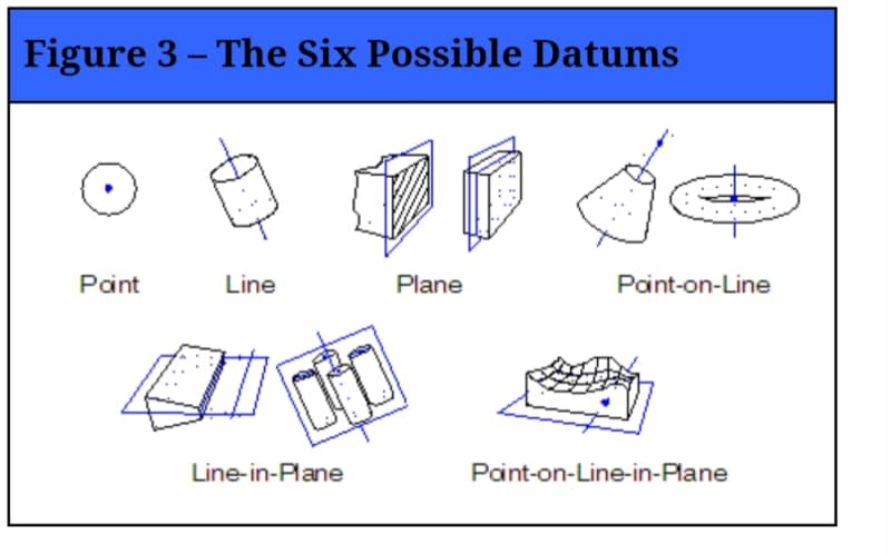
For example, usually a flat taper is defined by applying the concept of "common datum feature" (previously "multiple datum feature"). One face can be labeled B, the other C, and the feature referenced as B-C. Each face would be mated to a plane simulated by the fixture or a computerized process. These two planes and the line of their intersection can be considered the datum instead of the Line-in-Plane idea. It doesn't take too many skills to figure out how to relate such two planes and a line datum to two planes of the datum reference frame. Call that a "scribble" but sometimes you get multiple equally good ways to a solution. You should not always expect someone feeding you the only one way "allowed", be it Y14.5 or Tandler. At least Y14.5 doesn't try to tell you that the solutions shown in the 7-3 chart are the only types of datum you can ever use. They are presented as examples, contrary to Tandler's pretentious "The Six Possible Datums" from your preferred example.
 
Status
Not open for further replies.
Back
Top