does anyone have idea or references how to profile tolerance a complex trimmed edge on say a vac formed part? I don't really see any good examples in the standard to other places. Would it make sense to just point to the trimmed edge with a 'ALL OVER' profile tolerance with a note below that states "trimmed edge". using "all around" wouldn't work to me as it is controlled only in the view its shown in and a trimmed edge would go all around in 3d.
Navigation
Install the app
How to install the app on iOS
Follow along with the video below to see how to install our site as a web app on your home screen.
Note: This feature may not be available in some browsers.
More options
Style variation
-
Congratulations TugboatEng on being selected by the Eng-Tips community for having the most helpful posts in the forums last week. Way to Go!
You are using an out of date browser. It may not display this or other websites correctly.
You should upgrade or use an alternative browser.
You should upgrade or use an alternative browser.
profile on trimmed edge 8
- Thread starter DGN1975
- Start date
- Status
- Not open for further replies.
Burunduk
Mechanical
- May 2, 2019
- 2,580
Not "all over" because that would mean all over the part (including all features under that tolerance and not just the trimmed edge).
I don't have a very good suggestion for what may be the best way to specify it symbolically to make it look nice and professional.
I doubt that a note such as "ALL AROUND EDGE" may be misinterpreted here though.
I don't have a very good suggestion for what may be the best way to specify it symbolically to make it look nice and professional.
I doubt that a note such as "ALL AROUND EDGE" may be misinterpreted here though.
- Thread starter
- #5
Burunduk, It wouldn't work in the top view as then the trimmed edge would be 'kind of" normal to the page..as in I then would be trying to control the profile in and out of the page not left or right, up or down.
I added a top view so you can see what i mean. Maybe if I just did a detailed view and did a cross-hatch on the trimmed surface and noted that???
I think I know the standards well, but these complicated parts make me feel like I don't...
I added a top view so you can see what i mean. Maybe if I just did a detailed view and did a cross-hatch on the trimmed surface and noted that???
I think I know the standards well, but these complicated parts make me feel like I don't...
The problem is the standards morphed "PROFILE", a tolerance that applied to a projection of a curve along the view vector, into a general purpose surface offset control that is not necessarily associated with any vector. There is also a lack of definition for curvature continuous surfaces - it fact the opposite. If one applies "all around" to a rectangle the control applies across the curvature discontinuities. It should be obvious that pointing to the trimmed face and using all around would have supporting language.
Literally:
Clearly unclear. They have tried to paper over moving from 2D, view dependent descriptions and tolerancing for machined parts and are unable to deal with your case.
Your case does not meet any of the allowed applications.
Some will certainly leverage the word "may" and explain that this is not a limitation, that profile is like the genie and can grant any wish you like - but the 100% exclusion of alternatives in description or example says there is zero uniform interpretation offered by the standard.
Literally:
When a profile tolerance applies all around the true profile of the designated features of the part (in the view in which it is specified),
A model or a drawing view is created to show the true profile.
PROFILE
profile: an outline of a surface, a shape made up of one or more features, or a two-dimensional element of one or more features
Clearly unclear. They have tried to paper over moving from 2D, view dependent descriptions and tolerancing for machined parts and are unable to deal with your case.
Profile of a surface may be applied to parts of any shape, including parts that have a constant cross section as in Figure 11-6, parts that have a surface of revolution as in Figure 11-19, and parts that have a profile tolerance applied all over as in Figure 11-9.
Your case does not meet any of the allowed applications.
Some will certainly leverage the word "may" and explain that this is not a limitation, that profile is like the genie and can grant any wish you like - but the 100% exclusion of alternatives in description or example says there is zero uniform interpretation offered by the standard.
Burunduk
Mechanical
- May 2, 2019
- 2,580
DGN1975,
The ASME Y14.5-2018 standard defines the profile tolerance zone this way (11.3.1):
"Profile tolerances apply normal (perpendicular) to the true profile at all points along the profile. The boundaries of the tolerance zone follow the geometric shape of the true profile."
So, the fact that the "trimmed edge would be 'kind of" normal to the page.." shouldn't be a concern, the tolerance zone boundaries are not dependent on the view but are normally offset from the true profile. I suppose that for a complex part like that, a model defines the true profile, otherwise you would need a million basic dimensions to define that trimmed edge.
Here is how a similar case is shown in the standard:

Note that the reason they didn't show it with the all around symbol is that in their example the trimmed edge is considered one single surface that surrounds the part (no corners or rounds are included there).
The ASME Y14.5-2018 standard defines the profile tolerance zone this way (11.3.1):
"Profile tolerances apply normal (perpendicular) to the true profile at all points along the profile. The boundaries of the tolerance zone follow the geometric shape of the true profile."
So, the fact that the "trimmed edge would be 'kind of" normal to the page.." shouldn't be a concern, the tolerance zone boundaries are not dependent on the view but are normally offset from the true profile. I suppose that for a complex part like that, a model defines the true profile, otherwise you would need a million basic dimensions to define that trimmed edge.
Here is how a similar case is shown in the standard:

Note that the reason they didn't show it with the all around symbol is that in their example the trimmed edge is considered one single surface that surrounds the part (no corners or rounds are included there).
Burunduk
Mechanical
- May 2, 2019
- 2,580
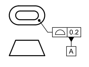
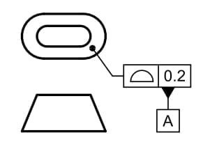
There should be no concern about the lack of a 2D view that shows the entire edge surface normal to the page. Below is a simpler case where no such view can exist, yet the edge surface could be fully dimensioned on the 2D drawing views that do exist or could be added, and no need to reference a model. This is from figure 7-3.

In my opinion they should have included the all around symbol in this case as the intended true profile is made of a flat taper and two conical rounds grouped together. So it does have an oversight, but the principle is clear.

In my opinion they should have included the all around symbol in this case as the intended true profile is made of a flat taper and two conical rounds grouped together. So it does have an oversight, but the principle is clear.
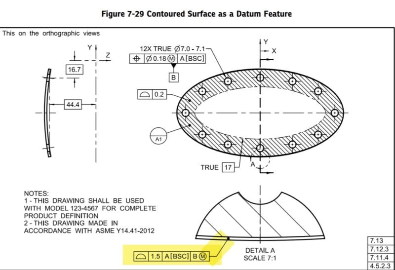
Of interest is 2018, Figure 7-29 is another example of the disconnections between various factions of the committee turning lack of review into an opportunity to further personal policy by ignoring both the definitions and ignoring the subcommittee responsible for the feature.
Does the part have constant cross section? Is the surface one of revolution? Is it applied all over?
The creators failed to add any reference to a Section 11, Tolerances of Profile paragraph, ensuring it went unaccounted for.
Does the part have constant cross section? Is the surface one of revolution? Is it applied all over?
The creators failed to add any reference to a Section 11, Tolerances of Profile paragraph, ensuring it went unaccounted for.
ME said:The problem is the standards morphed "PROFILE", a tolerance that applied to a projection of a curve along the view vector, into a general purpose surface offset control that is not necessarily associated with any vector.
Burunduk
Mechanical
- May 2, 2019
- 2,580
3DDave said:is another screwed up example and cannot represent what is claimed. Neither end is conical and the result is not a point.
Off-topic and at least partially incorrect.
Yes - as I wrote, if the OP uses ASME Y14.41 then it is allowable to use that faction's interpretation.
Y14.5 clearly does not support what you want it to even if the datum group doesn't pay any attention to the profile group.
All you needed was a yellow highlight over the Y14.41 note - and you ignored the need for that basis rule. Do better.
It would take a lot to fix the second example. Not spotting it immediately shows a problem with understanding orthographic projection. It is so blatant that I can offer it as evidence the committee pays little attention to their product.
Burunduk
Mechanical
- May 2, 2019
- 2,580
3DDave said:Y14.5 clearly does not support what you want it to even if the datum group doesn't pay any attention to the profile group.
Clearly it does and I already gave the reference - the definition for a uniform tolerance zone for a profile requirement.
It is not free of problems but it's got what's needed to deal with OP's case.
That was no basis rule but an example, which is apart from being relevant for the view-related concern, also addresses a complex geometry practically asking for a model to be part of the data set - guess what - just like OP's part. But even if a model and Y14.41 are not used, one could still define it all on 2D, as difficult as it might get with needing a multitude of basic dimensions, some of which could possibly be expressed mathematically to describe curves. In the OP's case a multitude of auxiliary views would be required too.3DDave said:All you needed was a yellow highlight over the Y14.41 note - and you ignored the need for that basis rule.
Not a lot at all - only a minor graphic issue. This is off-topic nitpicking.3DDave said:It would take a lot to fix the second example
You gave a definition for the zone that is predicated on establishment of the true profile which is predicated on the definition of profile, which this case fails on. Bad foundation = invalid result.
More example of this magical thinking that the committee depends on to cover their errors and sell more training.
I don't understand people who, when a defect is exposed, jump in to say "It's not a defect if it's in the book." It allows the creators of that book license and leeway to create further defective work.
This case has no outline of a surface from which a tolerance zone can be derived. The zone is a compound curvature surface that has no outline. It doesn't mean what you want it to mean.
Adding the additional "one could still define it all on 2D, as difficult as it might get with needing a multitude of basic dimensions" et al at this point demonstrates the failure to initially inform.
For someone who failed to recognize the datum feature example problem that also ignored the Profile subcommittee you seem too confident.
Burunduk
Mechanical
- May 2, 2019
- 2,580
There is no requirement for a 2D outline, or a problem with the compound curvature surface controlled for profile. Take another reference - read the definition of True Profile in the definitions section.
"Failure to initially inform"? How much spoon-feeding do you need?
"Failure to initially inform"? How much spoon-feeding do you need?
- Status
- Not open for further replies.
Similar threads
- Replies
- 6
- Views
- 3K
- Locked
- Question
- Replies
- 21
- Views
- 10K
- Replies
- 31
- Views
- 7K
- Locked
- Question
- Replies
- 24
- Views
- 4K
- Locked
- Question
- Replies
- 15
- Views
- 4K

