Continue to Site

Eng-Tips is the largest engineering community on the Internet

Intelligent Work Forums for Engineering Professionals

  • Congratulations KootK on being selected by the Eng-Tips community for having the most helpful posts in the forums last week. Way to Go!

Profile tolerance for location control

Status
Not open for further replies.

Sa-Ro

Industrial
Jul 15, 2019
273
IMG_20200614_013336_c8lq1j.jpg


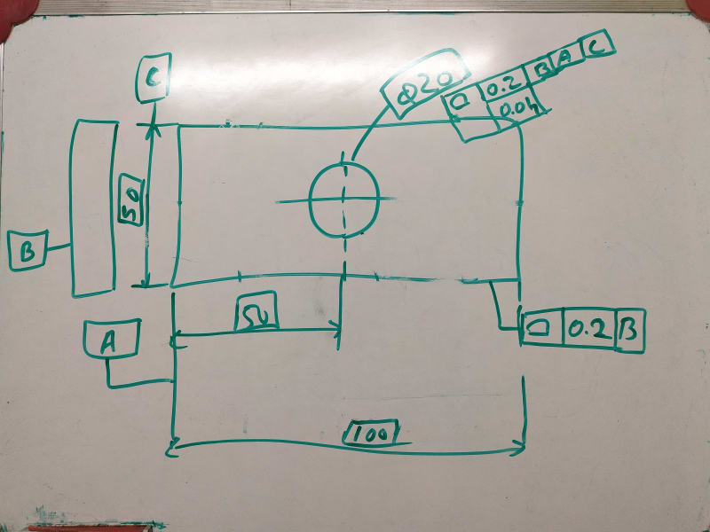
Profile tolerance with datum B, will control the 100 between 99.8 and 100.2 be parralel plane

50 between 49.8 and 50.2 by parallel plane

Clearly understood.

Dia 20 profile tolerance with B A C will control the circle between 19.9 and 20.1 by concentric circle.

0.04 will control the form.

Clearly understood.

How the location of circle (50) is controlled by profile tolerance. Whether by dia 0.2 or parallel plane 0.2.

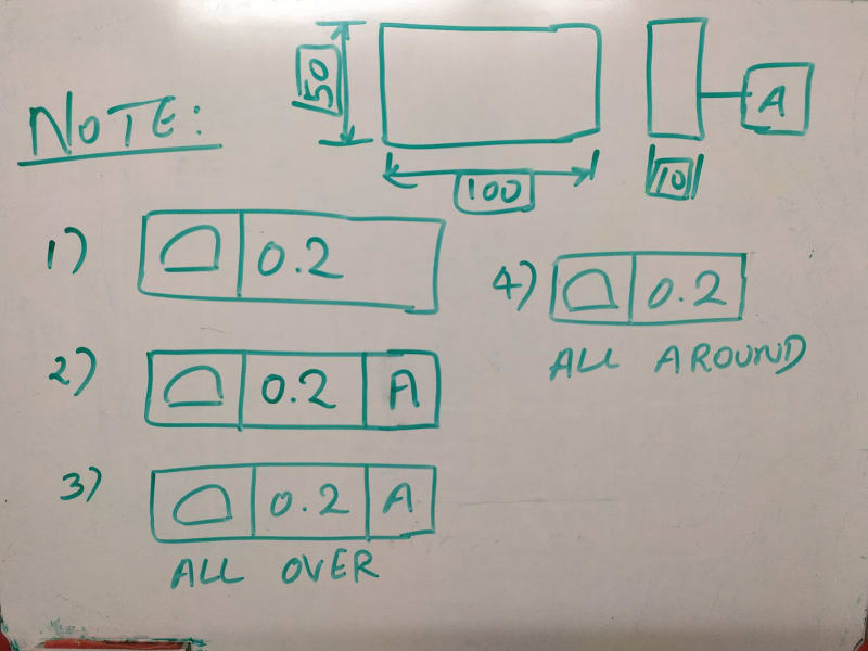
What is the meaning of profile of surface tolerance in general note

profile of surface and tolerance only

profile of surface, tolerance and datum(s)

Does all over / all around symbols must in general note / implied to all surfaces.
 
Replies continue below

Recommended for you

I guess in order to provide some meaningful answer here, you need to clarify what you are asking. I have no idea what is/ are your question(s).
The drawing is poorly made.
Is profile 0.2|B| applicable to the bottom feature or to the right feature?

and after that you just put some words together but no much significance in the English language.

What means these?

OP said:
How the location of circle (50) is controlled by profile tolerance. Whether by dia 0.2 or parallel plane 0.2.

What is the meaning of profile of surface tolerance in general note

profile of surface and tolerance only

profile of surface, tolerance and datum(s)

Does all over / all around symbols must in general note / implied to all surfaces.
No wonder why you didn't get any answers with such of bad problem statement


Agreed there are some issues with the drawing. You have questions about an all around profile symbol (as well as a general note, which is not shown on your sketch or provided in the body of your post to know what you're talking about) - if you wish the 0.2 profile to |B| to apply to all the surfaces which make up A and C then yes it needs the all around symbol attached to the leader line.

If you wish the composite profile to apply to the central 20mm feature, then it needs to be applied directly to it with a leader line NOT the dimension (right now its actually floating oddly next to the basic dimension - its not even clear what it applies to).

How the location of circle (50) is controlled by profile tolerance. Whether by dia 0.2 or parallel plane 0.2.

I too do not understand what you are asking here. Please clarify.
 
My apologize for poor problem statement.

ALL OVER symbol missed in profile 0.2 datum B.

As per standard, profile controls location.

Here the location 50.

If I applied position tolerance, the dia 0.1 tolerance zone wrt datum BAC.

What is the geometric tolerance shape of dia 20 location (50).

What will be the minimum and max location of the 50.

Is it 49.9 and 50.1?
 
General note question is different subject.

I have seen some drawing with general note as profile l tolerance l with or without datum.

Some other with all over and all around symbol.

What is that meaning?
 
IMG_20200615_201835_dgfbps.jpg


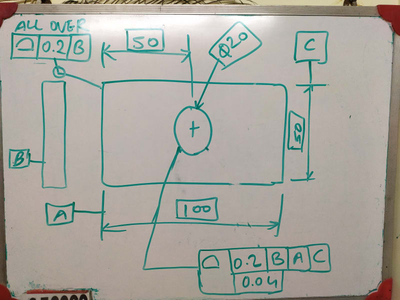
Here is corrected drawing.
 
IMG_20200615_202316_azeyad.jpg


What is the meaning of FCF?
 
What is the geometric tolerance shape of dia 20 location (50).

What will be the minimum and max location of the 50.

Is it 49.9 and 50.1?

Profile controls the surface of the feature, not the axis. There is some indirect limitation of how far the axis may deviate, but it is not a simple relationship like 50-(0.2/2) it would have to be modeled in CAD.

I have seen some drawing with general note as profile l tolerance l with or without datum.

Some other with all over and all around symbol.

What is that meaning?

Per the new Y14.5-2018 application of a profile tolerance in the general notes/tolerance block constitutes an all-over profile tolerance. Per Y14.5-2009 this is not explicitly stated, if your general note does not say "ALL OVER" or "UNLESS OTHERWISE SPECIFIED/UOS" the meaning may be implied, but I would say it is not clear.

Y14.5-2018 said:
11.3.1.5 All Over Specification.
A profile tolerance may be applied all over the three-dimensional profile of a part UOS. It shall be applied in one of the following ways:
(a) place the “all over” symbol on the leader from the feature control frame as shown in Figure 11-10
(b) place the term “ALL OVER” beneath the feature control frame
(c) place the profile tolerance requirement in the general tolerance block or general notes
 
Sa-Ro,

Your sketch on (15 Jun 20 14:50) is conflicting - you have the notation "ALL OVER" combined with an All Around symbol on the leader line. See the differences between the definitions and the symbols - you need to choose one. You can also use the symbol on the leader line OR the actual words (ALL OVER or ALL AROUND) attached to the FCF, but you should not use both it would be redundant.

Y14.5-2018 said:
11.3.1.3 All AroundSpecification.
When a profile tolerance applies all around the true profile of the designated features of the part (in the view in which it is specified), the “all around” symbol is placed on the leader from the feature control frame.
[...]
11.3.1.5 All Over Specification.
A profile tolerance may be applied all over the three-dimensional profile of a part UOS.

all_around_qzqfty.jpg


What is the meaning of FCF?

For 1,2, and 3 see my response above (15 Jun 20 15:00). 4 is not a valid specification in my mind, as the All-Around notation requires it be applied to a specific true profile in a specific view - if applied as a general note it is not clear what true profile it applies to.
 
It is ALL AROUND - Single circle only.
 
Thank you.

So for cylindrical feature, position tolerance is better to locate thru dia 0.1 than profile tolerance.
 
Presumably you are talking about the 0.2 profile tolerance to |B| on your (15 Jun 20 14:50) figure (context matters). If so you need to EITHER have "ALL AROUND" applied to the FCF OR have the All Around symbol (single circle) applied to the leader line. You should not have both.

Does the rest make sense?
 
So for cylindrical feature, position tolerance is better to locate thru dia 0.1 than profile tolerance.

It is not necessarily better, just different - it depends on what best communicates your design intent and best represents part function. At RFS position you control the axis. At RFS profile you control the surface.
 
Tomorrow I will share my recent drawing which I prepared based on your inputs.
 
Refer attachment

Design requirement:
1) Product will be placed on Datum A.
2) Dia 28 bore is used to locate the product.
3) Dia 6.6 holes is used to align and mount the product.
4) Outer edge of the component shall not project outside the product (56.5 X 72.5)
5) Datum E placed on customer machine.
6) Dia 6.35 hole used to locate the assembly.
7) Dia 6.35 slot used to align the assembly.
8) Dia 5.5 holes used to mount the assembly.

Did I communicated in drawing thru GD&T correctly?
 
 https://files.engineering.com/getfile.aspx?folder=426d144a-4fac-44b7-8a16-95c87892bdbf&file=1.JPG
Sa-Ro,

The drawing in your attachment is very hard to read. The resolution needs to be higher.

Evan Janeshewski

Axymetrix Quality Engineering Inc.
 
Sa-Ro,

The drawing is generally done well. Here are a few things I might have done differently:

1. In the composite position FCF for the 4X 5.5 holes, the lower segment should reference E instead of A

2. The symbol for ALL AROUND is a circle on the bend of the leader line.

3. The 6.35 hole and slot are tightly sized features that orient and locate the assembly. I would have used these as datum features, and toleranced some of the other features relative to those.

4. In the position tolerance for the 4X 11 mm counterbores, the reference to datum feature C is not necessary. Instead of composite position, the lower segment could have been perpendicularity.

5. In the composite position tolerance on the 4X 5.5 mm holes, the lower segment controls the pattern shape and spacing within 0.1 mm. This is quite tight for holes that just mount the part (I imagine that clearance fit fasteners pass through).

Evan Janeshewski

Axymetrix Quality Engineering Inc.
 
Status
Not open for further replies.

Part and Inventory Search

Sponsor