Continue to Site

Eng-Tips is the largest engineering community on the Internet

Intelligent Work Forums for Engineering Professionals

  • Congratulations KootK on being selected by the Eng-Tips community for having the most helpful posts in the forums last week. Way to Go!

Profile tolerance for location control

Status
Not open for further replies.

Sa-Ro

Industrial
Jul 15, 2019
273
IMG_20200614_013336_c8lq1j.jpg


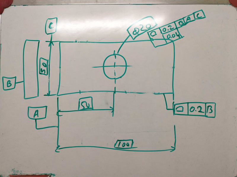
Profile tolerance with datum B, will control the 100 between 99.8 and 100.2 be parralel plane

50 between 49.8 and 50.2 by parallel plane

Clearly understood.

Dia 20 profile tolerance with B A C will control the circle between 19.9 and 20.1 by concentric circle.

0.04 will control the form.

Clearly understood.

How the location of circle (50) is controlled by profile tolerance. Whether by dia 0.2 or parallel plane 0.2.

What is the meaning of profile of surface tolerance in general note

profile of surface and tolerance only

profile of surface, tolerance and datum(s)

Does all over / all around symbols must in general note / implied to all surfaces.
 
Replies continue below

Recommended for you

Thank you.

1) I Missed that.

2) all around circle and all over circle not visible in print. Hence I decided to mention " ALL AROUND"

3) Dia 6.35 and 4X dia 5.5 are only accessible by customer.

4) you are right. Clocking not required at this feature. I have mention position tolerance in second compartment as perpendicularity.

5) it is for perpendicularity.
 
axym said:
Sa-Ro,

The drawing is generally done well. Here are a few things I might have done differently:

1. In the composite position FCF for the 4X 5.5 holes, the lower segment should reference E instead of A

2. The symbol for ALL AROUND is a circle on the bend of the leader line.

3. The 6.35 hole and slot are tightly sized features that orient and locate the assembly. I would have used these as datum features, and toleranced some of the other features relative to those.

4. In the position tolerance for the 4X 11 mm counterbores, the reference to datum feature C is not necessary. Instead of composite position, the lower segment could have been perpendicularity.

5. In the composite position tolerance on the 4X 5.5 mm holes, the lower segment controls the pattern shape and spacing within 0.1 mm. This is quite tight for holes that just mount the part (I imagine that clearance fit fasteners pass through).
Evan Janeshewski

Evan,

Let me stir the pot:

Ref 3.) I cannot see 6.35 holes. Maybe 6.3 but not 6.35 :)
The top surface feature of the part is dimensioned and toleranced with profile|0.1| and becomes datum A, then in the other view is shown another all around profile within 0.3|A|B(MMB)| and the FRTZF is |0.1|A|. Does not seem correct in my opinion, kind of redundant.

The 6.3 slot is not complete dimensioned. Either add another position in the vertical direction either move the existing position and show it with a leader line "Where the same positional tolerance
can be allowed for both, only one feature control frame is necessary, directed to the feature by a leader and separated from the size dimensions." 7.4.5.1.c / 2009

TYP word is not standardized verbiage. Use number of places such as 4x, 8x, etc


And one more question for you Evan,

Is the composite callout (as currently shown) even legal/ per the standard?

PLTZF TZ is zero but FRTZF TZ is 0.1. Shouldn't the TZ value in FRTZF be smaller than in PLTZF?

 
6.3 +0.05 / +0.15 = 6.35 / 6.45

greenimi said:
toleranced with profile|0.1| and becomes datum A

For flatness control.

greenimi said:
then in the other view is shown another all around profile within 0.3|A|B(MMB)|

For size control

greenimi said:
the FRTZF is |0.1|A|.

I am unable to understand.

greenimi said:
The 6.3 slot is not complete dimensioned. Either add another position in the vertical direction

Vertical tolerance is open.

 
OP said:
Vertical tolerance is open.

Well: "(a) Each dimension shall have a tolerance, except for those dimensions specifically identified as reference, maximum, minimum, or stock (commercial stock size)."


For a complete drawing requirements there is no such of open tolerance"

By the way: what means "open tolerance" ? It's a defined term in the stanndard?


Sa-Ro said:
Design requirement:
1) Product will be placed on Datum A.
2) Dia 28 bore is used to locate the product.
3) Dia 6.6 holes is used to align and mount the product.
4) Outer edge of the component shall not project outside the product (56.5 X 72.5)
5) Datum E placed on customer machine.
6) Dia 6.35 hole used to locate the assembly.
7) Dia 6.35 slot used to align the assembly.
8) Dia 5.5 holes used to mount the assembly.

This is how I would approach it based on my understanding of the above requirements (it will be mainly about datum features selection):

1. Keep datum feature A as is, but delete the all round 0.1 profile (it is partially redundant as the top and bottom faces of the part are also controlled with the all around profile in the other view). Replace it with a single flatness tolerance.

2. Keep datum feature B as is, but replace the position tolerance with perpendicularity as the hole does not have a location relationship to A. Also, I am curious where the 0.1 MAX requirement comes from. If it is justified from functional standpoint, put dia. 0.1 MAX in the same compartment as dia. 0(M), if the drawing is per Y14.5-2009 or 2018. If per 1994, leave it as is.

3. Define the pattern of four dia. 6.6 holes as datum feature C. Control it with position relative to |A|B(M)|. Remove C from the basic 56 width.

4. Each dia. 6.6 hole can still be defined as individual datum feature D to control position of the corresponding counterbore relative to |A|D(M)| individually and then refined with a perpendicularity callout relative to A, if needed.

5. Define the face opposed to A as datum feature E. Control it with profile relative to |A|. Make the dimension for the thickness of the part basic.

6. Keep datum feature F as is, but control it with position relative to |A|B(M)|C(M)| and refine with perpendicularity tolerance relative to E.

7. Define the width of the 6.3 slot as datum feature G and control it with position relative to |E|F(M)|.

8. Control the pattern of four dia. 5.5 holes relative to |E|F(M)|G(M)|.

Note: The MMB modifiers used in most of the callouts assume that there is no inteference between mating features in the entire assembly.
 
@ greenimi

Open tolerance means, as per general tolerance table in title block.

@pmarc
1) I missed that.

2) Since position tolerance can be used for perpendicularity control, I have used position tolerance.

Though the tolerance increase up to 0.21, I am restricting the tolerance to 0.1. In solid works, there is no option to specify inside the geometric tolerance box. They have provided adjacent box as "tolerance 2"

3) OK.

4) As it is.

5) OK.

6) Already there is 0.1 tolerance only. Refining with perpendicularity may tighten the tolerance.

7) as clocking required to align the slot with axis of datum B?

8) Yes. No mating surfaces except, datum A and datum E
 
OP said:
@ greenimi

Open tolerance means, as per general tolerance table in title block.

Do you have a title block for the location? I haven't seen that....Could you please show it. Thank you

Pmarc,

pmarc said:
7. Define the width of the 6.3 slot as datum feature G and control it with position relative to |E|F(M)|.

pmarc,

What is controlling the location of the bottom slot in the vertical direction (up and down)?

Do I miss its vertical location or its somehow implied or maybe is non existent? Seriously, I do not see a general profile for the attached drawing? Even there is one is it related to A|B(M)|C(M) or to |E|F(M)|G(M)|?
I suspect to the former and if that's the case the slot dimensioning scheme does not make much sense (its width to |E|F(M)| and its length to A|B(M)|C(M)|)

Do you understand what I am trying to say? I know you are very detail oriented and I would like to learn from you and your thinking / concept method.

 
OP said:
2) Since position tolerance can be used for perpendicularity control, I have used position tolerance.

Where does it say that? Which paragraph? Please advise.

In my opinion: "7.2 POSITIONAL TOLERANCING Position is the location of one or more features of size relative to one another or to one or more datums."

axym said:
I was initially going to say that using Position in this case would be inadvisable but legal, but it looks like you're correct that the standard does in fact disallow it. 7.2 states that Position is "the location of one or more features of size relative to each other or to one or more datums". We don't have location relative to each other, because there is only one feature. We also don't have location relative to a datum, because the feature is nominally perpendicular to the datum. So the standard says nay nay.

 
IMG_20200618_061528_zkmvwv.jpg


This is our general title block tolerance as per ISO 2768.

Since slot only for alignment with dia 6.35 and dia 28 holes, vertical dimension shall float within general tolerance.
 
So, this drawing is per ISO or per ASME? Please advise.

 
Sa-Ro,

2. Position is incorrect symbol to use because the feature B cannot be physically controlled for location relative to A, only orientation.

6. Perpendicularity relative to E is needed to be able to easily calculate the MMB size of F in E|F(M) datum reference frame.

7. Yes, I forgot to mention another position tolerance for the width. This one could be relative to A|B(M)|C(M).


greenimi,

The vertical direction of the slot would have to have a seprate position callout, which I did not mention because I mainly focused on mating features of the assembly.
 
pmarc,

Thank you for your late night answer. Appreciate it.

Lets see how the OP's standard (ISO or ASME) is coming out? Because if ISO, I suspect some callouts you proposed should/ shall be updated and revised.

If ASME, if would ask what kind of "practice" is to combine ASME definition with ISO 2768 (specially ISO 2768). Maybe if a combo ASME-ISO 13715 (corners, edge) I might understand, but 2768....no way!!!

Have a good night!

 
greenimi said:
Where does it say that? Which paragraph? Please advise

In many examples I have seen, flat surface as datum A and TP applied with dia 0.1 for hole axis.

As per standard also TP controls orientation.

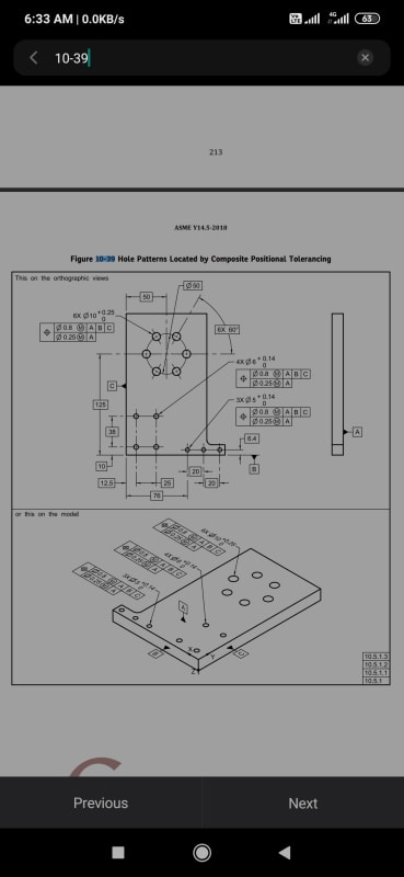
ASME Y 14.5:2018

Screenshot_2020-06-18-06-33-46-757_cn.wps.xiaomi.abroad.lite_qhx2ku.jpg


Correct me if I am wrong.
 
GD&T as per ASME Y14.5:2018.

General tolerance in title block in accordance with ISO 2768
 
OP said:
In many examples I have seen, flat surface as datum A and TP applied with dia 0.1 for hole axis.

There is no "hole axis" but "holes axes" !! (singular versus plural)
In the example you show from the standard there are multiple holes, but in your case it is only one hole (singular hole). Big difference.

Position is required if you want to control the mutual relationship between the HOLES!!


I am asking again, ISO or ASME?
Please provide complete details of your title block.
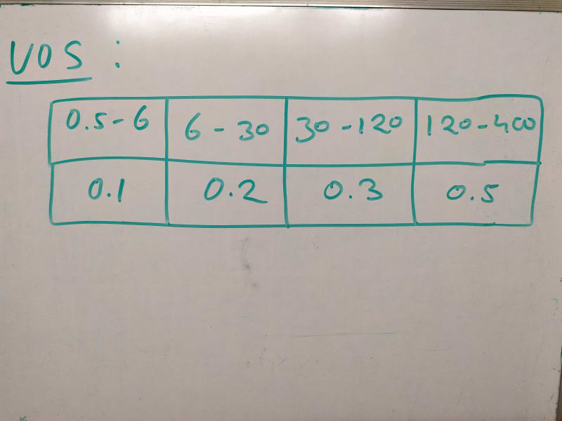
UOS and some numbers in the table does not help much. What are those numbers? Details, details

 
OP said:
GD&T as per ASME Y14.5:2018.

General tolerance in title block in accordance with ISO 2768

Wow!! That is interesting approach.
What is the tolerance class applicable?


Ok.

Today I will attach our title block.
 
Medium tolerance

But we have not mentioned any standard on drawing
 
either move the existing position and show it with a leader line "Where the same positional tolerance can be allowed for both, only one feature control frame is necessary, directed to the feature by a leader and separated from the size dimensions.

Is it possible to attach Position tolerance to surface - Since it is not controlling the surface?

If not possible, can you draw a sketch to explain your point.

3. Define the pattern of four dia. 6.6 holes as datum feature C. Control it with position relative to |A|B(M)|. Remove C from the basic 56 width.

I thought clocking feature required to orient the four holes as shown in drawing.

If four holes are defined as datum C - 4X individually, how to consider when

1) Counter bore is inspected - Each dia 6.6 hole is datum C for corresponding counter bore?

2) Dia 6.35 bore is inspected - four holes together act as datum C or individually - as acted to counter bore?

6. Keep datum feature F as is, but control it with position relative to |A|B(M)|C(M)| and refine with perpendicularity tolerance relative to E.

As a functional requirement, datum E will be placed on assembly bed while the dia 6.35 used to locate. That is why perpendicularity required to datum E.

7. Define the width of the 6.3 slot as datum feature G and control it with position relative to |E|F(M)|.

Shall I refer" TP|E|F(M)|B(M) - datum B for orientation?

6. Perpendicularity relative to E is needed to be able to easily calculate the MMB size of F in E|F(M) datum reference frame.

I guessed, TP|0(M)|E|B(M)|C(M) will locate and orient the feature.

Awaiting for your guidance...
 
Status
Not open for further replies.

Part and Inventory Search

Sponsor