Continue to Site

Eng-Tips is the largest engineering community on the Internet

Intelligent Work Forums for Engineering Professionals

  • Congratulations KootK on being selected by the Eng-Tips community for having the most helpful posts in the forums last week. Way to Go!

Profile tolerance for location control

Status
Not open for further replies.

Sa-Ro

Industrial
Jul 15, 2019
273
IMG_20200614_013336_c8lq1j.jpg


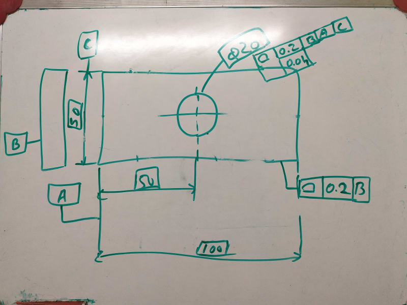
Profile tolerance with datum B, will control the 100 between 99.8 and 100.2 be parralel plane

50 between 49.8 and 50.2 by parallel plane

Clearly understood.

Dia 20 profile tolerance with B A C will control the circle between 19.9 and 20.1 by concentric circle.

0.04 will control the form.

Clearly understood.

How the location of circle (50) is controlled by profile tolerance. Whether by dia 0.2 or parallel plane 0.2.

What is the meaning of profile of surface tolerance in general note

profile of surface and tolerance only

profile of surface, tolerance and datum(s)

Does all over / all around symbols must in general note / implied to all surfaces.
 
Replies continue below

Recommended for you

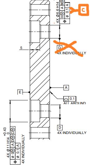
3. Based on your description of the design requirements, it looks to me that it is the pattern that should serve as tertiary datum feature C, not the width. If the pattern is tertiary (and if primary is a flat surface and secondary is a hole perpendicular to the face) there is no feature to orient from yet and there doesn't have to be, because that role will be taken exactly by the pattern once established as tertiary datum feature. This is how this could be done without getting rid of individual D's.

capture_vhoujb.jpg


6. Yes, you can say that this the functional reason why F should be controlled with perpendicularity to E. The other reason (about ease/possibility of calculation of MMB of F with respect to E) is still valid though.

7. I already answered that. My preferred choice would be to apply two position callouts to the slot width.
a) One relative to |A|B(M)|C(M)|.
b) Second relative to |E|F(M)|.
If you choose to control the slot with a single position relative to |E|F(M)|(B(M)|, my concern will then be that the determination of MMB size of B in that datum reference frame will be extremely difficult.
 
role will be taken exactly by the pattern once established as tertiary datum feature.

Yes. I agree, size dimension 56 is not locating feature. 4X dia 6.6 holes are locating feature - Datum C.

Sorry for more doubts.

Datum B is axes with two perpendicular plane which can rotate about datum B axes and perpendicular to datum A. then how clocking not required. In study materials also, explaining as "to orient a feature, clocking datum must be declared".

If 4 holes are not declared as tertiary datum, the orientation is required or not?

If dia 6.6 holes is datum C (without 4X INDIVIDUALLY) How to address each counter bore with corresponding dia 6.6 hole?

7.a) Dia 6.6 holes are nothing to do with 6.3 slot and datum A. Because datum E is placed on assembly bed, dia 6.3 hole and 6.3 slot is used to locate and orient the assembly. Dia 28 axes should be aligned with end function.

7.b) Horizontal position wrt datum |E|F(M)| - OK. But orientation with datum B?

MMB of datume B is 0 to dia 0.21 (28.21 - 28)
 
pmarc,

Sorry to bother you: two quick questions:

A.) Would you consider okay (legal) that in the composite callout there is zero 0(MMC) in the PLTZF and 0.1 in FRTZF?
B.) Would you agree that using ISO2768-m on an ASME Y14.5-2018 defined drawing is a good practice?


Also I find strange the OP's statement "But we have not mentioned any standard on drawing " I don't think that is an acceptable practice either.

What do you think/ recommend?

 
Sa-Ro said:
Datum B is axes with two perpendicular plane which can rotate about datum B axes and perpendicular to datum A. then how clocking not required. In study materials also, explaining as "to orient a feature, clocking datum must be declared".

It is the pattern C that would define the orientation. So the profile tolerance for the outer contour would have to reference A|B(M)|C(M) in order to have the outer contour oriented to the pattern.

Sa-Ro said:
If dia 6.6 holes is datum C (without 4X INDIVIDUALLY) How to address each counter bore with corresponding dia 6.6 hole?

Look again at my last crude illustration. I deleted D at the top hole and moved it to the hole at the bottom and this is where the entire definition on the Individually basis would be defined. The position tolerance for the counterbores would not require C, as mentioned earlier by Evan(axym) and it would have to be changed from composite to position + perpendicularity.

Sa-Ro said:
7.a) Dia 6.6 holes are nothing to do with 6.3 slot and datum A. Because datum E is placed on assembly bed, dia 6.3 hole and 6.3 slot is used to locate and orient the assembly. Dia 28 axes should be aligned with end function.

But there needs to be something that will orient the dia. 6.3 hole F and the 6.3 slot G with other features of the part. You want to use hole B for that. I say you should consider pattern of the dia. 6.6 holes.

Sa-Ro said:
7.b) Horizontal position wrt datum |E|F(M)| - OK. But orientation with datum B?

MMB of datume B is 0 to dia 0.21 (28.21 - 28)

This is not how MMB of B should be calculated. MMB of B represents a boundary that will not be violated by the surface of the hole B when the hole is considered with respect to the higher order datums, in this case |E|F(M)|. This will not be easy calculation, I can tell you.

 
pmarc said:
…...and it would have to be changed from composite to position + perpendicularity.

Ok. If you change from composite position to position + perpendicularity then by above question is no longer applicable.

The remaining questions are still 'alive"

 
Thank you for the detailed explanation.

Now I understood the concept.

1) Define datum A, flatness control 0.1.

2) Dia 28 bore - perp|dia 0(M) (dia 0.1 MAX)|A

3) 4X Dia 6.6 holes - TP|dia 0(M)|A|B(M) and perp|dia 0(M) (dia 0.1 MAX)|A - Two single segment FCF. Attach datum C to FCF.

4) Counter bore dia 11 - TP|dia 0(M)|A|B(M)|C(M) and perp|dia 0(M) (dia 0.1 MAX)|A - Two single segment FCF

5) 56 X 72 basic dimension - Profile of surface | 0.3 | A|B(M)|C(M) - ALL AROUND

6) Thickness 10 basic dimension - Composite tolerance: Profile of surface | 0.2 | A and Profile of surface | 0.1. Attach datum D to opposite face of datum A.

7) Dia 6.3 hole - TP|dia 0(M)|D|C(M) - Attach datum E

8) 6.3 slot - TP|0(M)|D|E(M)|C(M) - Horizontal direction only - attach datum F

9) 6.3 slot - TP|0.2(M)|D|E(M)|C(M) and - Vertical direction only - Not important - shall refer general tolerance in title block.

10) 6.3 slot - Profile of surface | 0.15 U 0 | D|E(M)|F(M) - ALL AROUND - How to define 0.05 to 0.15 instead of 0.15

11) 4X Dia 5.5 hole - TP|0(M)|D|E(M)|F(M)

Tomorrow I will update the drawing and attach.
 
OP said:
6) Thickness 10 basic dimension - Composite tolerance: Profile of surface | 0.2 | A and Profile of surface | 0.1. Attach datum D to opposite face of datum A.

7) Dia 6.3 hole - TP|dia 0(M)|D|C(M) - Attach datum E

8) 6.3 slot - TP|0(M)|D|E(M)|C(M) - Horizontal direction only - attach datum F

9) 6.3 slot - TP|0.2(M)|D|E(M)|C(M) and - Vertical direction only - Not important - shall refer general tolerance in title block.

10) 6.3 slot - Profile of surface | 0.15 U 0 | D|E(M)|F(M) - ALL AROUND - How to define 0.05 to 0.15 instead of 0.15

11) 4X Dia 5.5 hole - TP|0(M)|D|E(M)|F(M)

Tomorrow I will update the drawing and attach.

Yes, please update the drawing because some of the callouts I copied above do not make much sense,
(E is from D|C| , but then in another callout such as 9- is secondary and then C is tertiary). Seems illogical to me.

Per pmarc, #9 should be to A|B(M)|C(M) and not |0.2(M)|D|E(M)|C(M)|


greenimi said:
A.) Would you consider okay (legal) that in the composite callout there is zero 0(MMC) in the PLTZF and 0.1 in FRTZF?
B.) Would you agree that using ISO2768-m on an ASME Y14.5-2018 defined drawing is a good practice?


Also I find strange the OP's statement "But we have not mentioned any standard on drawing " I don't think that is an acceptable practice either.

What do you think/ recommend?

A. Was already answered by me, as you noted.

B. I don't think it is necessarily a bad practice to define general tolerances for linear dimensions based on a different standard - ISO 2768-1 in this case - if done correctly and consciously. In this case, as far as I understand, the general tolerance block is defined without even giving a reference to 2768-1. I don't see anything fundamentally wrong with that.

To me the more concerning is the fact that there is no standard defined on this drawing at all. This literally means that when it comes to intepretation of the applied dimensioning and tolerancing all bets are off. Especially that by just looking at the way how the dimensions and tolerance frames are currently displayed on the face of the drawing, one could have easily thought that ISO is in charge here.
 
Pmarc,
Full disclosure: my pet peeve (and based on other posts might be yours too)

Datum feature B is H11, datum feature C (the pattern of 6.6 holes) is H14.
Based on those info, how do you know or why do you think datum feature B is acting like translation constraining feature only and datum feature C will act like rotation constraining feature ?
Why A|B(MMB)|C(MMB)| and not A|B(MMB)-C(MMB| ?

I have the same "fight" with Rich Cruz on linkedin ETI group and still not won or lost it.

Anyway, it is not the hill I want to die on, but I am just curious about your qualified opinion.....
 
Here the updated drawing. PFA.

Design requirement:
1) Product will be placed on Datum A.
2) Dia 28 bore is used to locate the product.
3) Dia 6.6 holes is used to align and mount the product.
4) Outer edge of the component shall not project outside the product (56.5 X 72.5)
5) Datum E placed on customer machine.
6) Dia 6.35 hole used to locate the assembly.
7) Dia 6.35 slot used to align the assembly.
8) Dia 5.5 holes used to mount the assembly.

In addition to above, dia 28 and dia 6.3 holes are to be aligned. Axes from dia 28 will be connected to end application.
 
 https://files.engineering.com/getfile.aspx?folder=ab029227-ec9f-4c27-b40f-57228d52c4d9&file=Flange.PDF
Kedu,
Yes, this has been my pet peeve too. I just did not want to add it to this particular discussion as I think there are more fundamentals problems to solve before we can even get to this type of advanced and philosophical topics (especially that even Y14.5 does not seem to have a problem with it).
 
Couple of observations regarding the latest drawing attached:

i.) duplicate datum feature C: remove C from 56 width basic dimension

ii.) Ø6.3 top hole is not related to the main coordinate system A|B(M)|C(M)|. Should as use a position to A|B(M)|C(M)| and a perpendicularity to D and this hole, as shown become E. Obviously, remove current shown position to D|C(M)| which does not make any logical sense.

iii.) slot width should be dimensioned as explained by pmarc, 6.3 width positioned to D|E(M)| and become F.
currently shown position to D|E(M)|C(M)| is illogical and, as stated by pmarc the MMB boundary cannot be calculated (at least not easy)

iv.) bottom slot height/length location should be shown from its height's of length's extremities and not attached to 2mm dimension. Should be from A|B(M)|C(M)| or from D|E(M)|F(M)|. I prefer the latest, but if pmarc has his strong arguments I can accept the former too.

v.) If you got rid of the INDIVIDUALLY callouts for the C'bore and for its applicable datum feature its okay, but I hope you realize now the design is more stringent. If functionally this stringency is needed or not you have to decide.

vi.) Composite profile for D can be replaced with a profile single segment within 0.2 and flatness within 0.1. In my opinion this is more straight forward than the composite.

vii.) Why on Ø5.5 H14 holes you have H14 and also +0.3/0. Is it needed? If yes, shouldn't be within parenthesis ()?
 
Sa-Ro,

I notice you have covered this new drawing with "MAX" notation. What is your reasoning behind limiting the MMC position tolerance to a certain maximum value in every case? I can see some reasons why one might want to utilize this, however it seems to me it would be the exception not the rule as in most cases it is an undue restriction on the available MMC tolerance and prevents the effective use of hard gauging. Especially not for something as simple as a bolt clearance hole and counterbore. You even have it applied to at least two RFS position tolerances which by definition cannot exceed the tolerance specified in the FCF (or perhaps you mistakenly specified RFS instead of MMC).

Also the position tolerance applied in the vertical direction for the slot is incorrectly applied, it must be applied to the physical feature not the center to center distance of the radiused ends. See Y14.5-2009 fig 7-34 for proper MMC position applied to a slot.
 
Dia 5.5 H14 0.3 provided for discussion only. Usually we provide Dia 5.5H14 only.

No functional requirement for MAX. It can be removed.

Thank you for your support.

One more point.

How you gained this much knowledge in GD&T.

I too red ASME Y14.5 - 2018 standard book two times and didn't understand the concept well.

Is there any other method / resource to improve my GD&T skill?
 
I don't know much GD&T, but I came here to learn (from pmarc in this particular discussion).
Remember the entire concept has been proposed and reviewed by pmarc and I am just rephrasing what I agree/ or disagree with (but, from my experience is very hard to disagree with pmarc:))
So, if there is any credit due, please give it to pmarc.

One more technical aspect for your latest drawing posted: 1x45° and 2x45° chamfers should both dimensions be basic (1, 45 and 2 shall be basic) because you are using all around profile for the outer perimeter of the part.
All around text should be replaced by a small circle (see pictures from the standard for proper drafting)


Sa-Ro,

D&T (from the title of the Y14.5 standard) was invented to deal with a particular problem seen at the time. If you haven't seen the sort of problems that D&T is intended to solve, it won't be meaningful.

For most people the only D&T "problem" they have is they are required to put something on a drawing so that an inspector will say purchased parts meet those requirements, without much concern for whether the parts function. Some people work up to simply fitting parts together, which is mainly covered by profile and position tolerances on top of the Envelope Principle.

It's rare that someone says they have done a stress/strength/deflection analysis to show that a part will fail when the surfaces are beyond some particular shape limitation.

For example - the distance between the crank and wrist pin holes in a connecting rod in an engine affects the compression ratio - how many people have calculated the change in pollutants and effects on engine efficiency to set the limits on that distance?

It's equally rare that people have a large amount of factory production performance data to tell what variations they need to design around.

The best way to learn is to understand the things you are trying to design and the variations that affect how they are installed and the functions they perform. Then you can look at the standards for applicable controls.
 
Status
Not open for further replies.

Part and Inventory Search

Sponsor