Continue to Site

Eng-Tips is the largest engineering community on the Internet

Intelligent Work Forums for Engineering Professionals

  • Congratulations waross on being selected by the Eng-Tips community for having the most helpful posts in the forums last week. Way to Go!

Projected Tolerance Zone / Maximum Material Boundary

Status
Not open for further replies.

weavedreamer

Automotive
Aug 1, 2007
279
I'm hoping these are fairly straightforward.


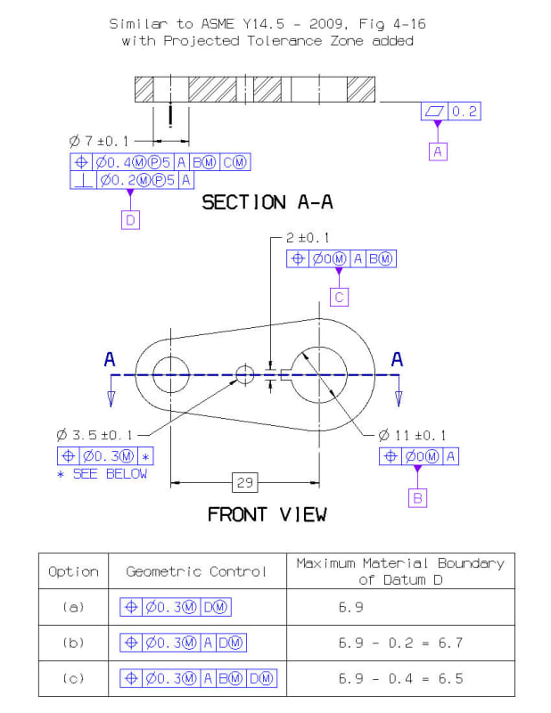
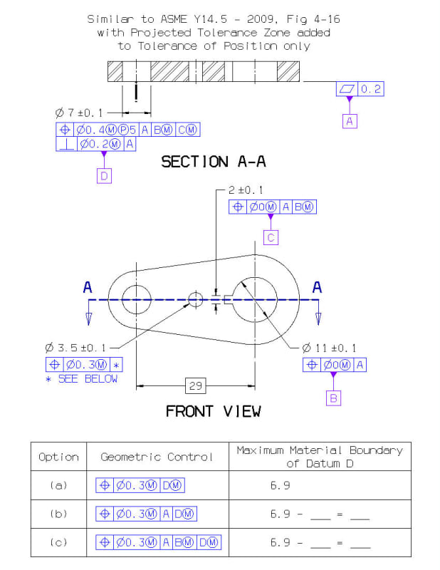
***** Image 1 *****
DNR0001248_RL-1_lxf95a.jpg


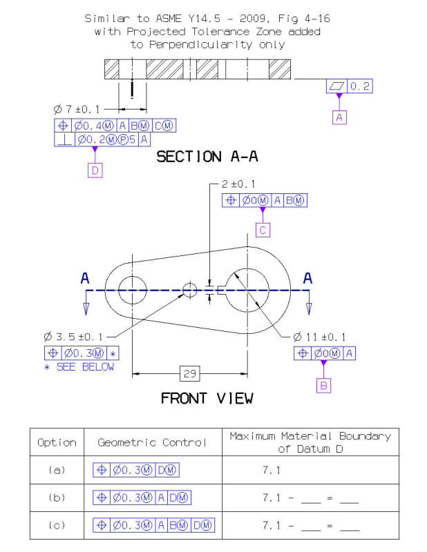
***** Image 2 *****
DNR0001248_RL-2_dwlse5.jpg


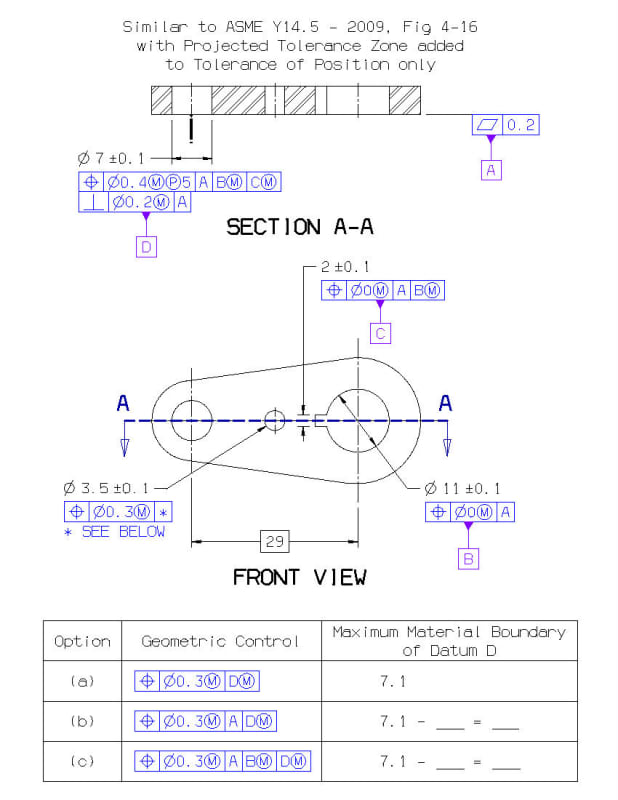
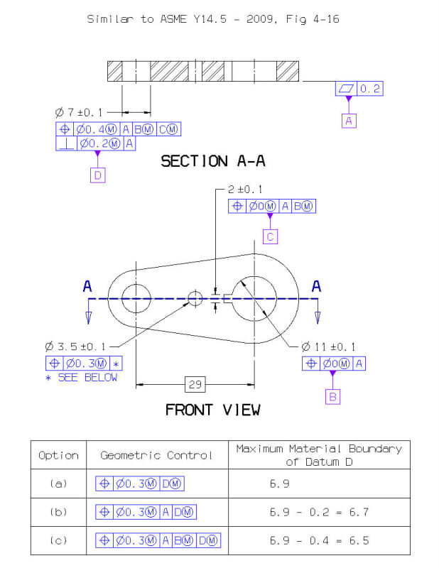
***** Image 3 *****
DNR0001248_RL-3_wmenep.jpg


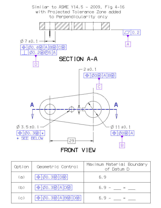
***** Image 4 *****
DNR0001248_RL-4_ens3ag.jpg


Is there an approach to calculating the Maximum Material Bound when the Projected Tolerance Zone is only used on the positional geometric control or just the perpendicularity geometric control?
 
Replies continue below

Recommended for you

I don't see how the starting point will be dia 7.1.
 
I don't think this can be answered correctly without knowing the maximum possible thickness of the part.

Also, cases 2(b) and 2(c) don't look OK.

3(a) and 4(a) should simply be 6.9.
 
***** image 3 correction *****
DNR0001248_RL-3_kvilsa.jpg


***** image 4 correction *****
DNR0001248_RL-4_h28sth.jpg


That was missed after converting the O.D. of a wall from the ASME example to the I.D. of a hole in this variation.

tim_member, the part thickness adds a divisional branch into the approach. Keeping the PTZ of 5 mm, how would a part thickness of 2.5 mm or alternatively 10 mm influence the result respectively?
 
Shortly speaking, the thicker the part the smaller the size of MMB of datum feature D. Thickness of the part matters because maximum material boundary of datum feature D resides inside the part (hole), not outside of it, and so its size (diameter) changes as the thickness of the part changes.

I am quite sure that a precise math formula can be found for this relationship.
 
tim_member:

We rarely use (P) in our designs. I understand the basics but I have not studied the "consequences" of (P) very much. Let me try to understand what you are saying:

By definition the (P) tolerance zone (TZ) is "above" the metal. But the virtual condition (VC) is in the metal. So the VC calculation would use the diameter of the TZ when the (P) TZ is projected "down" into the metal. This would be a reduced diameter. And as you stated the thicker the part material the smaller the diameter in the metal - ratios and all that stuff. Is this correct?

Certified Sr. GD&T Professional
 
weavedreamer,

MMB datum feature references are based on boundaries that are fixed at true position, but MMC projected position tolerances are based on boundaries that are allowed to move. Why would you want to apply both concepts to the same feature? I'm having a hard time imagining a good reason.

What lead you to ask this question?


pylfrm
 
By definition the (P) tolerance zone (TZ) is "above" the metal. But the virtual condition (VC) is in the metal. So the VC calculation would use the diameter of the TZ when the (P) TZ is projected "down" into the metal. This would be a reduced diameter. And as you stated the thicker the part material the smaller the diameter in the metal - ratios and all that stuff. Is this correct?

I'm not sure that its being asked that I provide an explanation, however I think it helps me understand the concepts better so here goes.

Per Y14.5.1-1994 the term Virtual Condition doesn't seem to apply to projected tolerances - see section 5.3. What is actually utilized is the "Verification Volume" with a boundary of perfect form called the "Verification Boundary" which exists over the feature height whose axis must fall within the projected tolerance zone, which of course exists over the specified projected height.

The diameter of this Verification Volume is the following:
For MMC -> MMC size
For LMC -> LMC size
For RFS -> UAME size

This means essentially that for MMC/LMC the boundary is of fixed size but not fixed at basic location/orientation with respect to the DRF as we typically expect with MMC/LMC (ie: Virtual Condition) - therefore it can float with respect to the DRF, tolerance zone, and feature. The feature conforms as long as there exists a Verification Volume whose axis lies within the projected tolerance zone and the feature does not violate the Verification Volume. For RFS it is similar to what we expect with a typical RFS tolerance - since the diameter of the Verification Volume is essentially the UAME and is oriented to/makes contact with the feature of interest.

MMB datum feature references are based on boundaries that are fixed at true position, but MMC projected position tolerances are based on boundaries that are allowed to move.

pylfrm - am I correct in my above assessment? If so, can a feature defined with a projected tolerance at MMC be referenced at MMB?

Also something which bothers me about the references to projected tolerance in Y14.5-2009 and 2018, they all include which looks like threaded fastener or holes for what I assume to be press fit pins controlled at MMC. In fact even the note on fig 6-11 (2009) / 9-11 (2018) specifically states that additional bonus tolerance provided by specifying the thread at MMC may be "reduced or negated" by the centering effect of the threads when assembled to a fastener (when torque is applied). I would think that except for some obscure applications the RFS is really the only thing which makes sense and to me really drives the requirement for projected tolerance in the first place (orientation/location error which is exacerbated at some height above the feature due to constraint of a mating part with the feature of interest) - and certainly for the practical application of a threaded/torqued fastener or press fit pin.

Is there any real practical reason why MMC projected tolerance is utilized besides to allow simpler "functional" (fixed size) gauging and ignoring the realities of assembly? Or is this an oversight of the committee?
 
pylfrm - am I correct in my above assessment? If so, can a feature defined with a projected tolerance at MMC be referenced at MMB?

Your description of the tolerance definition appears to be correct. I'm not convinced that the term "virtual condition" doesn't apply though. Perhaps it wasn't used, but that's not proof of much.

I don't think ASME Y14.5-2009 places any explicit restrictions on the application of material boundary modifiers to datum feature references. A more important question is whether it defines the datum feature simulator geometry. I find the standard's explanation rather unclear, but I'd wager the intent is that the datum feature simulator for D in OP's examples be the largest cylindrical pin that is guaranteed to fit at true position with respect to higher-precedence datum features if the datum feature tolerances are satisfied. The diameter of such a pin can indeed be calculated, but the equation is more complicated than OP probably hoped.


Is there any real practical reason why MMC projected tolerance is utilized besides to allow simpler "functional" (fixed size) gauging and ignoring the realities of assembly? Or is this an oversight of the committee?

Perhaps you have an assembly where screws clamp two parts together. Part A has threaded holes, and part B has unthreaded through-holes. You might be willing to accept interference between the screw bodies and the holes in part B, but only when the screws are tight. A projected MMC position tolerance might make sense for the holes in part A in this case.

Perhaps you have an assembly where quick-release pins hold two parts together. Part C is on the side with the retaining balls, and has close-fitting clearance holes. Part D is on the side with the handles, and has loose-fitting clearance holes. A projected MMC position tolerance might make sense for the holes in part C in this case.


pylfrm
 
Your description of the tolerance definition appears to be correct. I'm not convinced that the term "virtual condition" doesn't apply though. Perhaps it wasn't used, but that's not proof of much.

Glad to see I'm on the right track in understanding projected tolerances, they're definitely slightly more complex than I initially thought, but not overly so - your comment about projected MMC tolerance defining "boundaries that are able to move" prompted me to delve into the topic a little more deeply and I'm glad I did.

I can see what you mean by the term "virtual condition" perhaps still being applicable even though its not mentioned in the referenced section. Would you say that for projected position the virtual condition in this case would be the movable boundary defined by the verification volume, or instead a boundary fixed at basic location/orientation relative to the DRF? I would almost certainly say the latter, I just don't want to assume anything. This would be consistent with the standard's definition of virtual condition:

ASME Y14.5-2009 said:
A positional tolerance defines either of the following:
(a) a zone within which the center, axis, or center
plane of a feature of size is permitted to vary from a true
(theoretically exact) position
(b) (where specified on an MMC or LMC basis) a
boundary, defined as the virtual condition, located at the
true (theoretically exact) position, that may not be violated
by the surface or surfaces of the considered feature
of size

I don't think ASME Y14.5-2009 places any explicit restrictions on the application of material boundary modifiers to datum feature references. A more important question is whether it defines the datum feature simulator geometry.

Duly noted about the lack of restrictions on material boundary modifiers. I was more asking if the combination of fixed and movable boundary concepts (per your previous comment) was valid. If we accept that it is, and we accept that the concept of virtual condition is also applicable per the above, then it seems to me calculation of MMB would follow closely from that. When you say "whether it defines the datum simulator geometry" are you suggesting that different interpretations are possible?


In regards to the practical examples for MMC projected tolerance, thank you for providing those explanations. I could see how limited interference to the shank of a threaded fastener might be acceptable depending on the application - though I would consider it less than ideal. For the pin application I can also accept that as a valid use of MMC projected position - the standard specifically mentions press-fit pins though to their credit does not specify a material condition in conjunction with it. I guess I just thought it strange that all the examples for projected tolerance utilize MMC when in my mind in most cases RFS, while more difficult to gauge, would better reflect the assembly condition.
 
pylfrm (Mechanical) 23 Jul 19 02:17 said:
weavedreamer,

MMB datum feature references are based on boundaries that are fixed at true position, but MMC projected position tolerances are based on boundaries that are allowed to move. Why would you want to apply both concepts to the same feature? I'm having a hard time imagining a good reason.

What lead you to ask this question?

pylfrm

Pins being pressed into the parts are showing a 'drift', rather than assuming the c/l of the hole being pressed into.
The hunch is that the application of the PTZ to refine the perpendicularity is allowing it to actually be fabricated with the 'drift' predisposed into the process. Picture the portion of the perpendicularity in the positional tolerance zone, but when it gets to the projected zone, it is no longer bound by the positional zone, almost as if the PTZ tolerance can be added to the positional, rather than a refinement within the positional as Perpendicularity is wont to do, less the PTZ modifier.

ASME Y 14.5-2009 7.4.1. appears to support the hypothesis when stating in the last paragraph:
"Where a composite or multiple segment feature control frame is used, the projected tolerance zone symbol shall be shown in all applicable segments."​
 
weavedreamer,

I don't know if its just because its a Monday or what but I find it very hard to follow the entirety of what you're saying/asking. Perhaps someone else can suss out your meaning better than I.

Pins being pressed into the parts are showing a 'drift', rather than assuming the c/l of the hole being pressed into.

First off, if your application requires press fit pins I think RFS is more applicable. Your parts are not "assuming the c/l of the hole being pressed into"? As in the axis of the hole before the pin is pressed is significantly different than the axis of the dowel pin when it is pressed in? To me it sounds like one or a combination of a few options, instead of some magical "drift":

1) Hole/pin axis is being incorrectly measured/evaluated
2) Significant form/straightness variation of the hole, pin, or both causing unexpected variation when mated
3) Press fit is too heavy or performed incorrectly causing bending/distortion of the pin or mating part
4) A combination of 2 and 3

The hunch is that the application of the PTZ to refine the perpendicularity is allowing it to actually be fabricated with the 'drift' predisposed into the process. Picture the portion of the perpendicularity in the positional tolerance zone, but when it gets to the projected zone, it is no longer bound by the positional zone, almost as if the PTZ tolerance can be added to the positional, rather than a refinement within the positional as Perpendicularity is wont to do, less the PTZ modifier.

I'm not sure I follow...

ASME Y 14.5-2009 7.4.1. appears to support the hypothesis when stating in the last paragraph:
"Where a composite or multiple segment feature control frame is used, the projected tolerance zone symbol shall be shown in all applicable segments."

I believe the portion you quoted is in relation to the literal application of the (P) symbol in the FCFs of a composite or multiple single segment tolerance, that it must be specifically called out in each segment for a projected tolerance zone to be applied (ie: (P) symbol in an upper segment does not imply that any lower segments also describe projected tolerance zones). I'm not sure how this relates to your hypothesis, though it might help if I understood what that was in the first place...
 
Pins being pressed into the parts are showing a 'drift', rather than assuming the c/l of the hole being pressed into.

I fail to see the connection between this and your MMC / MMB questions.

Are you trying to to determine the proper tolerances to ensure some particular functionality, or are you just stuck trying to interpret a drawing you have no control over? What is your goal?


The hunch is that the application of the PTZ to refine the perpendicularity is allowing it to actually be fabricated with the 'drift' predisposed into the process. Picture the portion of the perpendicularity in the positional tolerance zone, but when it gets to the projected zone, it is no longer bound by the positional zone, almost as if the PTZ tolerance can be added to the positional, rather than a refinement within the positional as Perpendicularity is wont to do, less the PTZ modifier.

Adding a perpendicularity tolerance will not make a position tolerance less restrictive. The two tolerances must both be met, and they can generally be considered independently.


Would you say that for projected position the virtual condition in this case would be the movable boundary defined by the verification volume, or instead a boundary fixed at basic location/orientation relative to the DRF?

Who knows. ASME Y14.5-2009 Section 7 implies that "virtual condition" is the tolerance boundary itself, and that it's located at true position. This is incompatible with the Y14.5.1M-1994 definition of MMC projected tolerances. The term is never used in Section 4 regarding datum feature references, so perhaps it doesn't really matter for the topic at hand.


When you say "whether it defines the datum simulator geometry" are you suggesting that different interpretations are possible?

I am suggesting that for the MMB modifier to make sense on a datum feature reference, the standard needs to define the geometry of the datum feature simulator that would be used. An attempt to do that is made, but unfortunately it's spread across multiple paragraphs that don't seem to fit together quite right.


I guess I just thought it strange that all the examples for projected tolerance utilize MMC when in my mind in most cases RFS, while more difficult to gauge, would better reflect the assembly condition.

Even stranger is that the "This on the drawing" portions of Y14.5-2009 Figs. 7-21 and 7-22 have MMC modifiers, but the "Means this" portions appear to describe RFS tolerances.

As far as I can tell, Y14.5-2009 never attempts to define the meaning of MMC projected tolerances. It doesn't give much of an explanation for RFS either, but the intended meaning is easy enough to guess in that case.


pylfrm
 
ASME Y14.5-2009 Section 7 implies that "virtual condition" is the tolerance boundary itself, and that it's located at true position. This is incompatible with the Y14.5.1M-1994 definition of MMC projected tolerances. The term is never used in Section 4 regarding datum feature references, so perhaps it doesn't really matter for the topic at hand.
[...]
I am suggesting that for the MMB modifier to make sense on a datum feature reference, the standard needs to define the geometry of the datum feature simulator that would be used. An attempt to do that is made, but unfortunately it's spread across multiple paragraphs that don't seem to fit together quite right.

I think I see the conflict you are referring to, since the tolerance boundary for a projected tolerance is the "verification volume" per Y14.5.1-1994 and for MMC is movable but per section 7 the virtual condition is the tolerance boundary but is fixed at true position. It can be one or the other, but not both. As you say though, pinning down what exactly is the virtual condition may be unimportant in this case. Considering this, I agree with your second statement about the lack of definition as to what the geometry of such MMB datum feature simulators would be - intuitively we can imagine this as you put it (from your post 27 Jul 19 03:39) "the largest cylindrical pin that is guaranteed to fit at true position with respect to higher-precedence datum features if the datum feature tolerances are satisfied" but it is not explicitly defined. If such a simulator is truly desired, I imagine it would probably be best to somehow define this on the print or auxiliary internal standard.

I'm not sure where in the standard "an attempt to do that is made" as you say though - I didn't see anything in 2009 or 2018 about projected tolerance in the applicable datum section (2009 section 4, 2018 section 7). Perhaps you're referring to some inferences that don't directly mention projected tolerance?

Even stranger is that the "This on the drawing" portions of Y14.5-2009 Figs. 7-21 and 7-22 have MMC modifiers, but the "Means this" portions appear to describe RFS tolerances.

As far as I can tell, Y14.5-2009 never attempts to define the meaning of MMC projected tolerances. It doesn't give much of an explanation for RFS either, but the intended meaning is easy enough to guess in that case.

I wholeheartedly agree with this. The sections related to projected tolerance in Y14.5 seem to be somewhat of a mishmash of concepts - its really only through reviewing Y14.5.1 that I got a complete, not to mention consistent, interpretation of how an MMC projected tolerance behaves.
 
chez311,

The attempt I was referring to relates to MMB in general, not projected tolerances in particular. I mainly had the last sentence of ASME Y14.5-2009 para. 4.11.6 in mind, but paras. 1.3.4, 4.5, 4.5.1, 4.5.2, and possibly others are also involved.


pylfrm
 
Adding a perpendicularity tolerance will not make a position tolerance less restrictive. The two tolerances must both be met, and they can generally be considered independently.
Perpendicularity is a refinement, agreed, when applied within the positional tolerance zone.

pylfrm said:
I fail to see the connection between this and your MMC / MMB questions.

Are you trying to determine the proper tolerances to ensure some particular functionality, or are you just stuck trying to interpret a drawing you have no control over? What is your goal?
I'm trying to understand the relationship between the hole location before a dowel is pressed into it, and the dowel positioning and orientation after pressed.

I think I now see that the MMB for the hole is not impacted by the Projected Tolerance Zone.
There is still some confusion on how to take perpendicularity into account when determining max and min shift and how it differs in the various examples.

Ultimately, the desire is to state the location of the pins back to the datum structure that the hole for pressing them into was initially stipulated.
 
I'm trying to understand the relationship between the hole location before a dowel is pressed into it, and the dowel positioning and orientation after pressed.

This screams RFS/RMB to me. Interference/press fits are one of the few times RFS/RMB accurately reflects the real world mating condition for a FOS. I'm having trouble understanding why your questions center around MMC/MMB - I've enjoyed discussing the topic with pylfrm and it has expanded my understanding of projected tolerance zones, but I'm not sure how it applies to your case.

I think I now see that the MMB for the hole is not impacted by the PTZ.

Where did you get this impression?

Side note - the abbreviation "PTZ" is not utilized in either Y14.5 2009 or 2018 (the latter of which makes increased use of abbreviations). While we often utilize nonstandard abbreviations in these discussions and TZ is commonly used to refer to Tolerance Zone - PTZ could refer to Position Tolerance Zone, Perpendicularity Tolerance Zone, Profile Tolerance Zone, or Projected Tolerance Zone (which I think is what you mean here). I would recommend being more specific.
 
This screams RFS/RMB to me. Interference/press fits are one of the few times RFS/RMB accurately reflects the real world mating condition for a FOS. I'm having trouble understanding why your questions center around MMC/MMB - I've enjoyed discussing the topic with pylfrm and it has expanded my understanding of projected tolerance zones, but I'm not sure how it applies to your case.

Because the drawings currently stipulate MMC and MMB's.

- as to being more specific, I'm still trying to frame the right question.
I've been going thru some older notes on applying this stuff in stacks, and realized there was not an example given the Projected Tolerance Zone as part of a composite callout. The sketches provided thus far are the permutations that appear to be possible.
 
Status
Not open for further replies.

Part and Inventory Search

Sponsor