Continue to Site

Eng-Tips is the largest engineering community on the Internet

Intelligent Work Forums for Engineering Professionals

  • Congratulations waross on being selected by the Eng-Tips community for having the most helpful posts in the forums last week. Way to Go!

Proper composite callout for this?

Status
Not open for further replies.

ronj100

Mechanical
Apr 22, 2013
33
Is this the correct way to GD&T this?
The dowel hole must have a tight positional tolerance to the center locating ring, and that it is in this orientation to the indicating edge (-B-) of the fixture. The indicating edge has to be orientated tightly horizontally to the pattern, but can have a larger positional tolerance in the Y axis.
Thanks
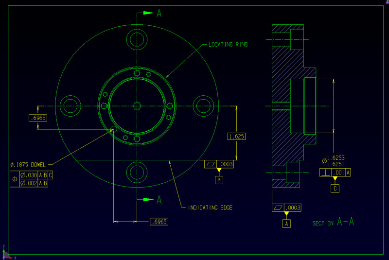
FIXTURE_tdzlpe.jpg
 
Replies continue below

Recommended for you

And inserting this before the next two comments, what is the pertainent standard. Now, presuming an ASME framework:

The perpendicularity callout is missing a diameter symbol, or a reference to datum B if it is orientation sensitive.

Is the XY indicator at the lower left supposed to be related to the view calling out the locating ring?

 
This is probably better expressed with two different FCFs. All you are effectively doing with this is tightening up perpendicularity to A to .002. Location is still within .030. Is this the entire drawing because nothing is controlling where the center is from the edge. I see a basic 1.625 from the edge and a perpendicularity to control the orientation but there's no locational tolerance that I can see. Since teh edge is secondary, you should control the holes to it rather than vice-versa. I see no control over the holes either.

John Acosta, GDTP Senior Level
Manufacturing Engineering Tech
SSG, U.S. Army
Taji, Iraq OIF II
 
yes, diameter symbol is missing. Thanks
Ignor the cad interface axis. It is part of the cad system, not part of the drawing.
Any suggestions on my actual question?
 
I removed all dimensions from the drawing that I thought were not essential to my question.
The indicating edge needs to be controlled because the machine operator uses a dial indicator to square up the fixture on the cnc machine.
The critical part of this fixture is the center locating ring and the dowel hole location, and that the indicating edge is orientated to that pattern as shown.
So I want to control the "orientation" of the indicating edge to the pattern, but have a large freedom of location of that edge in the y axis.
 
Well, as I said. The location of your dowel hole is only controlled to within .030. I don't know if that's what you're after or not.

John Acosta, GDTP Senior Level
Manufacturing Engineering Tech
SSG, U.S. Army
Taji, Iraq OIF II
 
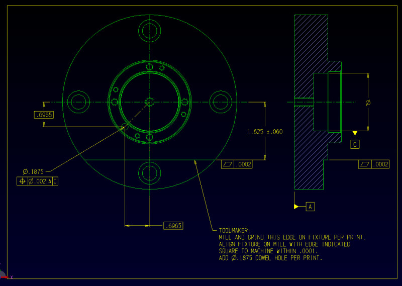
Let me start over.
How can I tolerance the orientation of the edge to the dowel hole and datum c without having to use a note like this?
PRINT2_f7iomf.jpg

Hope this helps
 
If you make that flat datum feature B again and reference B in the feature control frame that controls the dowel hole location, that will control the location of the dowel hole to within .002.

John Acosta, GDTP Senior Level
Manufacturing Engineering Tech
SSG, U.S. Army
Taji, Iraq OIF II
 
Status
Not open for further replies.

Part and Inventory Search

Sponsor