Continue to Site

Eng-Tips is the largest engineering community on the Internet

Intelligent Work Forums for Engineering Professionals

  • Congratulations KootK on being selected by the Eng-Tips community for having the most helpful posts in the forums last week. Way to Go!

Proper drafting/dimensioning practices

Status
Not open for further replies.

heli_eng28

New member
Nov 1, 2019
7
There's a bit of a debate in the office regarding dimensioning drawings. We bounce around back and forth between how drawings are dimensioned. Sometimes it's dependent on which machinist will be manufacturing the part, sometimes it depends on the manufacturing method, and sometimes it depends on the what the engineer ate for breakfast. One of our older engineers doesn't even know how to create a proper dimensioned drawing and forwards everything to us.

We DO NOT use GD&T currently. I've tried applying some dimensioning guidelines from GT&D, but I'll get kickback from the machinists on certain parts/dimensioning schemes about having to calculate dimensions, among other complaints.

A lot of the older drawings use hidden lines and we've been moving away from that. Some guys want them, some don't. Is there a standard on that? Some guys complain about dimensions on the part, others don't. Is it okay to have dimensions on parts?

Some guys like hole to hole dimensions, others like dimensions off a common datum so they don't have to calculate anything. I guess that's dependent on the design intent of the part and what dimension you're trying to hold exactly.

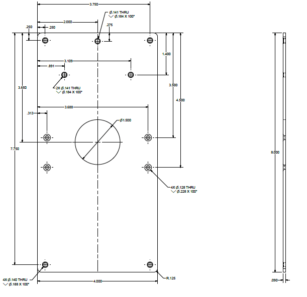
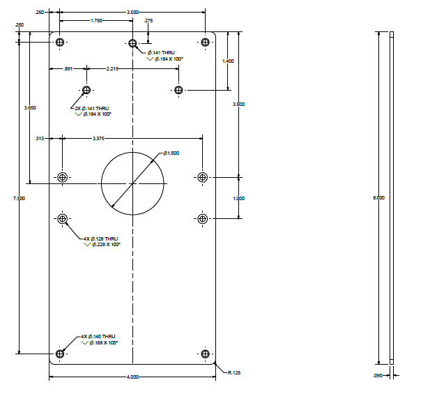
I've attached two drawings. Is either one more correct than the other?
Dwg1_bs8gpq.png


Dwg2_gntt4z.png


This document is a bit more advanced then some of the others I've come across online and covers a good bit of information:
Are there any others like this that are more advanced?
 
Replies continue below

Recommended for you

It's a mix of the two.
Drawings need to be made correctly so that any machinist can understand them and make the part.
Per your dwg, the sides are not square, the large circle does not indicate a C'Bore or thru, the R.125 on corner only indicates one corner (although all show a R).
It's these little things that add up and you can receive a bad part.

ctopher, CSWP
SolidWorks '17
ctophers home
SolidWorks Legion
 
Yeah, there are a lot of things that are implied on some of our drawings. We make it work, but it could cost us a lot of money if we send it to an outside vendor.

I personally didn't even know things like the large circle feature need a thru call out. We only use depth call outs on smaller holes (mainly anything with a fastener going through it).

I'm currently working on putting together a set of standards for our department to follow. I'd like to gather a bunch of resources from here and around the web to put it together. I'd also like to get us all trained on GD&T one day down the line.

 
If you don't depend on any standard, then what difference does it make? If you wish to follow the Y14 series of standards you need to buy them.

"GD&T" is a marketing term; the name of the Y14.5 standard is "Dimensioning and Tolerancing", there's no "G" in there, so you cannot be trained in "GD&T".
 
Regarding "THRU, per Y14.5 it is only required if it is not obvious that the hole is through the part.
I would remove "THRU" from the other callouts.

"Know the rules well, so you can break them effectively."
-Dalai Lama XIV
 
heli_eng28,

If you are dimensioning everything from a datum, use ordinate dimensions. This results in a cleaner, more readable drawing. I originally started dimensioning from datums when machinists told me how they set up on their milling machines. Datum (or ordinate) dimensions are easy to inspect manually, since you can fixture your part to the datum and just do one set of measurements. Back in my drafting board days, I used my programmable calculator to work out the XY[ ]coordinates of pitch circles. I figured it was more efficient than having the machinist work it out even once, much less every time. Everybody uses CNC now, and they ask for DXF and STEP files so that they can use the CAD geometry. Fabricators like hole tables. SolidWorks' hole tables are remarkably robust.

Now, I lean more towards showing design intent, i.e. pitch circles and such. With 3D[ ]CAD, you can easily apply whatever dimension scheme suits your purposes.

Usually, I do not show hidden lines. It makes for cleaner, simpler drawings. If hidden lines enhance clarity, I show them. In SolidWorks (and I am sure, the other CAD packages), I can show hidden lines of selected features. Usually, this clarifies the stuff I judge to be confusing. Maybe you need a section view! Your hidden lines clearly show you have countersinks, not centrebores.

Your two drawings look as legal as drawings can that do not specify standards. The really important thing ASME Y14.5 does is define what all your numbers and symbols mean. If you call up the ASME or ISO standards, a competently prepared drawing tells the vendor and your inspectors precisely what you want and are ready to pay for.

I try very hard to not place dimensions on top of the drawing view, as you have done above. Almost invariably, I succeed. This improves the readability of your drawing. Your object lines should be thicker than your dimension, centre and phantom lines.

I firmly believe that fabrication drawings should be prepared by the designer. The designer know how the part must work. Any problems the drafter encounters with too-tight tolerances and bad tolerance stacks, are design problems, not drafting problems. The design does not work, and the designer needs to fix it. This may involve wiggling tolerances around, or it may involve a re-think of the design. If your designer cannot read or prepare drawings, they cannot do mechanical design.

Drafting is not a process. It is communication. There is a discipline to clear communications. Most of the rules of good writing apply to drafting. Talk to your fabricators and inspectors. You need to know what they read efficiently and what they understand.

--
JHG
 
ewh said:
egarding "THRU, per Y14.5 it is only required if it is not obvious that the hole is through the part.
I would remove "THRU" from the other callouts.

I flipped through the manual yesterday and came across that. I guess technically you don't need any thru call outs on a thin plate because you most likely won't be drilling holes to a certain depth. It's pretty obvious everything is through the part.

Drawoh, thanks for the detailed response. Yeah, our machinists primarily set a zero from a datum and base the dimensions off that. I need to put together an introductory course for newer guys, because I've found when we take interns in from the local aviation school, the drawings get a little confusing for them. Especially stuff like ordinate dimensioning. They don't specifically train them in reading parts and running machines. That's something our company does when we take them on board.

I'll keep some of your points in mind and pass them along so we can get some more standardized and cleaner drawings out to the shop. I appreciate the response!
 
I agree about "Thru". But, the top image is not obvious that the holes are thru, the second image it is.
I also agree about having the dim's on top of the view. I always move them outside the view. I also try not to show hidden lines, a section view is better as needed.

ctopher, CSWP
SolidWorks '17
ctophers home
SolidWorks Legion
 
Thru is only needed if it is not obvious. Showing the hidden lines of the holes in the side view makes the holes obvious.
I was taught to leave the part object visible and put all dimensions around the part, not on it.
Dimensioning between holes is a function of the intended use. If these holes are used to mount another part, then I would dimension one hole from the edge of this part and the other holes from that hole. This will control the spacing better and avoid tolerance stack-up issues.


"Wildfires are dangerous, hard to control, and economically catastrophic."

Ben Loosli
 
My two cents --- Assuming you have stated on the drawing that Y14.5 is the "dictionary" used to read the drawing: The depth symbol is all that's needed to indicate a blind-hole. The lack of a depth symbol is by default a THRU hole, so the word THRU us redundant.

Certified Sr. GD&T Professional
 
Regardless of Y14.5 (which I use), a machinist can read drawings different ways. A lot of them don't know Y14.5. If you don't call out the depth of a hole, they can read it Thru or something else like a C'bore.
It's best to use the depth symbol or use Thru, to make it clear to them.

ctopher, CSWP
SolidWorks '17
ctophers home
SolidWorks Legion
 
I disagree Chris... if a hole is called out in a .090 thick sheet, I would worry if the machinist interpreted the callout as a c'bore. If they thought otherwise because "it wasn't obvious", I would be looking for another machinist. Without a depth specified, the default would be THRU. Again, the aim of a drawing is to provide a clear, concise part definition subject to only one interpretation.

"Know the rules well, so you can break them effectively."
-Dalai Lama XIV
 
ewh,
I do agree with you.
I'm going by my experience. I have too many machinists at various companies/vendors make the parts wrong because of this.
Good Machinists are a dying breed.

ctopher, CSWP
SolidWorks '17
ctophers home
SolidWorks Legion
 
Status
Not open for further replies.

Part and Inventory Search

Sponsor