Eng-Tips is the largest engineering community on the Internet

Intelligent Work Forums for Engineering Professionals

PSV Reaction Forces 4

Status
Not open for further replies.

kurtz

Mechanical
Sep 10, 2016
34
0
0
PL
Please look at the picture. Is it necessary to assume any other force from opening the safety valve?
I've seen some people add force directly at the outlet of the safety valve.

psv_n4ioa0.jpg
 
Replies continue below

Recommended for you

Forces and moments can be translated to any point of interest.

A 100N vertically applied downward force at x = 1m when translated to x=4m is equivalent to a
100N downward force plus a moment of 100N x (4m-1m) = 300 Nm

“What I told you was true ... from a certain point of view.” - Obi-Wan Kenobi, "Return of the Jedi"
 
Yes ...it is necessary..If the PSV opens, the pressure in the piping at outlet flange will be PSV pressure set value and will be zero at exit. If you are looking for design forces say at outlet flange , the resultant forces at flange conn will be;
Fx = p*A Fy= P.A and MZ= Fy* X A=area of exit piping , X = distance between exit point and flange.

If you are looking for the analysis of forces, you should define the control volume (say exit flange and exit point ) and write the momentum equation in X direction and Y direction.
 
That appears to be a very poor design. There will be a very high moment on that tee which could rupture the tee.

This is what happens when it goes wrong. See also report.

image_m4tvgq.png


Remember - More details = better answers
Also: If you get a response it's polite to respond to it.
 
HTURKAK said:
If the PSV opens, the pressure in the piping at outlet flange will be PSV pressure set value

If the PSV opens, the pressure in the piping at outlet flange will be the back-pressure created by the pipe, fittings, and elevation changes of the tailpipe.

Good Luck,
Latexman
Pats' Pub's Proprietor
 
Yes I believe you do (momemtum change)

With that orientation you still have a moment on the tee due to forces on the pipe in the span between the valve and your support. You may want to consider a seocnd support on the horizontal length from the valve to that first tee.

Also as the photo / report shows, the supports for the tail pipe failed so it need to be really strong.

Why the zig zag though?? seems very odd.

Remember - More details = better answers
Also: If you get a response it's polite to respond to it.
 
if that is a big valve, try to do something like this
psv_ahqtc5_ciikf0.jpg


“What I told you was true ... from a certain point of view.” - Obi-Wan Kenobi, "Return of the Jedi"
 
Thank you. What if I have fix support? Reaction force F1 = F2 ???

psv_kw6dkb.jpg


ax1e: Thak you. I published this post at the same time as you.
 
with a strongly fixed support there that is probably all you need, but please, it is your responsibility to verify.

“What I told you was true ... from a certain point of view.” - Obi-Wan Kenobi, "Return of the Jedi"
 
"with a strongly fixed support there that is probably all you need, but please, it is your responsibility to verify."

I checked in book Pipe Stress Engineering by Peng, but there is no clear answer.
 
Like I say, probably OK.
Magnitudes of thurst loads after being transmitted through pipe beyond strong supports (especially fixed) are not entirely clear, but should be markedly reduced. I build the supports for double the thrust loads, thereby making it unlikely that any significant force is being resisted by the pipe beyond.

Hint: When things are not entirely clear, draw it like you think it should be, then build it twice as strong as that. The guys that took the picture wish they followed that advice. :)

“What I told you was true ... from a certain point of view.” - Obi-Wan Kenobi, "Return of the Jedi"
 
But why the zig zag?

This is most unusual and adds moments and forces all over the place.

Remember - More details = better answers
Also: If you get a response it's polite to respond to it.
 
Has everybody read ASME B31.1 Appendix II ???

It is all explained there ....

I have always enjoyed these third world postings where the questions and diagrams get endlessly revised...

"What I meant to say ..."

"What I left out of my last posting..."

"What about if ...."

"I have been so busy, I forgot to tell you ..."


MJCronin
Sr. Process Engineer
 
It's a "highly fluid environment".

“What I told you was true ... from a certain point of view.” - Obi-Wan Kenobi, "Return of the Jedi"
 
This is a very interesting question. Some of our users ask me for it, but I'm not sure what to answer. ASME B31.1 Appendix II has no clear recommendations about it.
My opinion is that when PSV opens, the unbalanced pressure forces should be applied step-by-step in the direction of the flow. It should be similar to slug flow or water hammer.

I think that for the safest design we need to consider all 4 situations step-by-step:

2020-07-03_17-46-43_sjzlbf.jpg


But ASME B31.3 V1 and P1 equations are provided only for option (2) and used to check the outlet flange force.

I think option (1) is usually not considered, because the bending moment will lower than for option (2).

But in case if you put the sliding support (not anchor) under the vent pipe to take the load (2), the force (1) can still make the piping to fall off the supports. So maybe it makes sense to take the load case (1) into account...

For (3) and (4) I think we need to use the surge analysis in fluid flow software to get the V and P values.


If the truth be told, I think you have something there. If the pipe and fittings were push-ins/water pipeline type bell/spigot, we'd need a thrust block at every change in direction and it would have unbalanced forces at each joint, so the sum of all forces gets overwhelming. Best to have pipe configs as straight as possible and corresponding supports in the right places. The picture above shows what can happen if you don't. Pipe clamps in the wrong plane don't help. It appears that some forces were "redirected".

“What I told you was true ... from a certain point of view.” - Obi-Wan Kenobi, "Return of the Jedi"
 
ax1e,
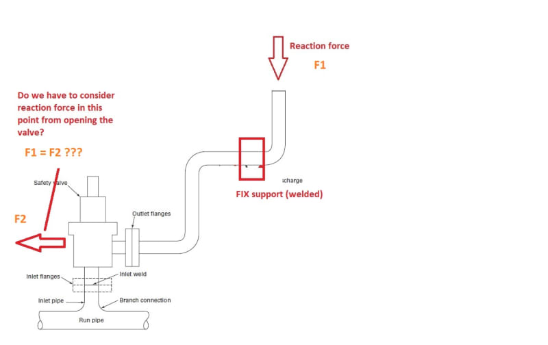
Yes, but the main question is how to determine the V and P values and how to apply it to model the unbalanced force effect correctly. After that we can decide how to place the supports to avoid the problems.
This is a very interesting question for me. Did anyone tried to model this situation in fluid flow software to determine P and V values? Or most of engineers just use the recommended approximate equations from ASME B31.1, EN 13480-3, API 520, GOST 33960, Rudomino article, L.C. Peng handbook?

I'm the PASS/START-PROF Pipe Stress Analysis Software Developer
 
With regard to Alex's diagram.
Forces at valve end (Edit) depends on the leg length. B31.1 App 2 implies that (Forces anywhere but the open end) edit *** can be ignored if leg length to the first elbow is less than 4 pipe diameters AND the pipe is constant diameter. (*** Previously listed as F1 because referring Alex's 3 Jul not Kurtz 10 Jun). I assume this is because the action time for the out of balance force is very small. (Process engineers often insist that reducers are put between the valve and first elbow. I have never come across a realistically accurate method of calculating the reaction force with a butt weld reducer). Process engineers claim to have a watch making precision for pressure drop. However, they are clueless when it comes to explaining the flow regime and reaction forces.
The formula in Alex's 3 Jul diagram 2 is for an open end with a shock wave. If the pipe is constant diameter, the shock wave, if it exists, could only be at the end of the constant diameter.
 
Status
Not open for further replies.
Back
Top