Continue to Site

Eng-Tips is the largest engineering community on the Internet

Intelligent Work Forums for Engineering Professionals

  • Congratulations SDETERS on being selected by the Eng-Tips community for having the most helpful posts in the forums last week. Way to Go!

PT Circular Floor 7

Status
Not open for further replies.

struggle66

Civil/Environmental
Jul 5, 2013
127
PT_Circular_Floor_k41zt8.png


Hi Good Day Everyone,

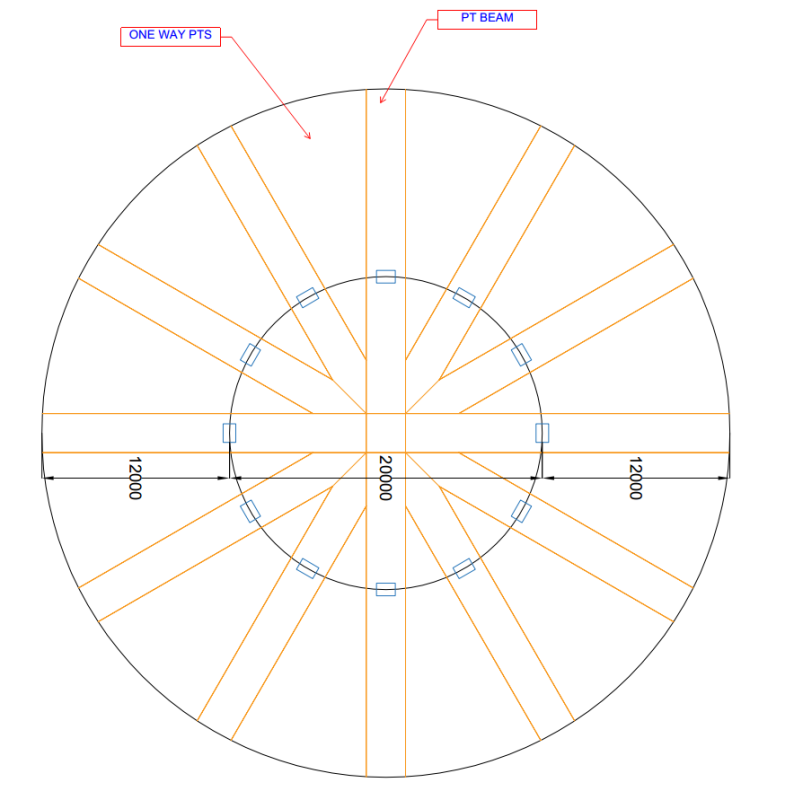
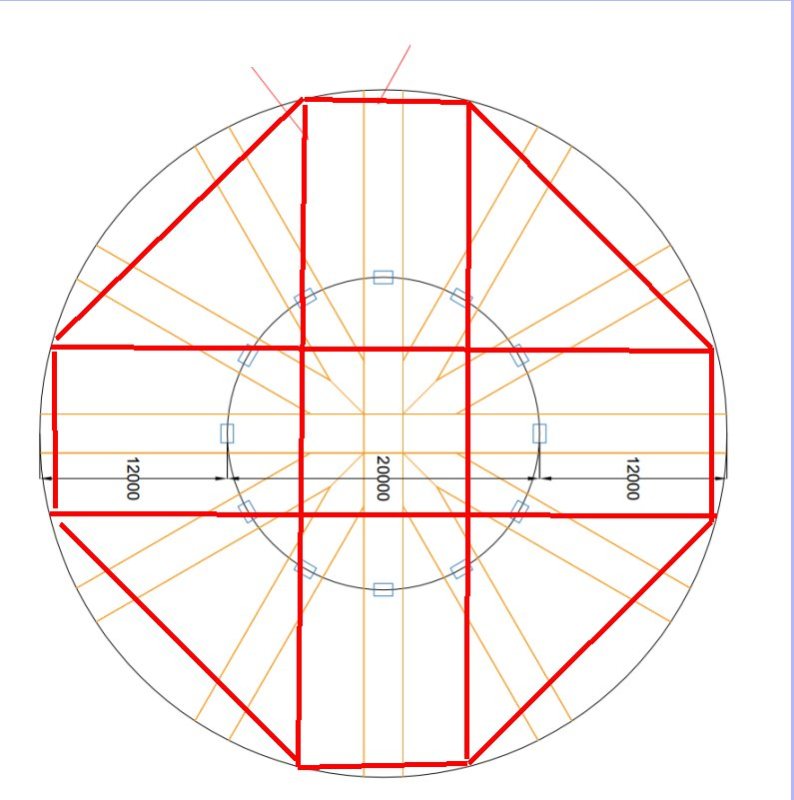
I've got to propose PT layout for above circular PT layout for a residential building with 12m cantilever on each side (Columns are only allowed on inner circle perimeter). I am thinking to propose as above but if that so except the rebar & tendon congestion @ the center of the circle, there will be a lot of pre-compression (P/A) due to PT & a lot beam design will share the section. It is my first time to encounter this kind of layout.

How should I approach, analysis & design? Thanks in advance for your help.

Thanks
 
Replies continue below

Recommended for you

I would start with how would a normal circular slab be reinforced and then I would work from there with a PT slab.

"Programming today is a race between software engineers striving to build bigger and better idiot-proof programs, and the Universe trying to produce bigger and better idiots. So far, the Universe is winning."
 
Struggle66 said:
I've got to propose PT layout for above circular PT layout for a residential building with 12m cantilever on each side

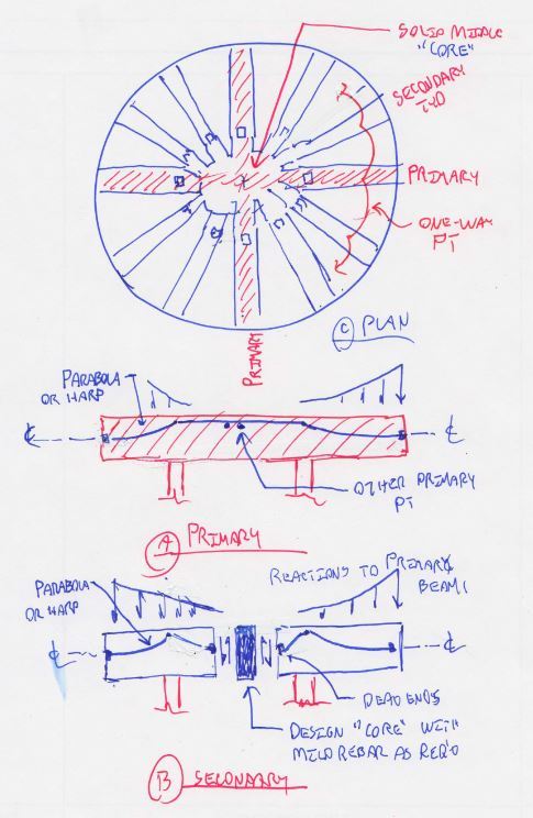
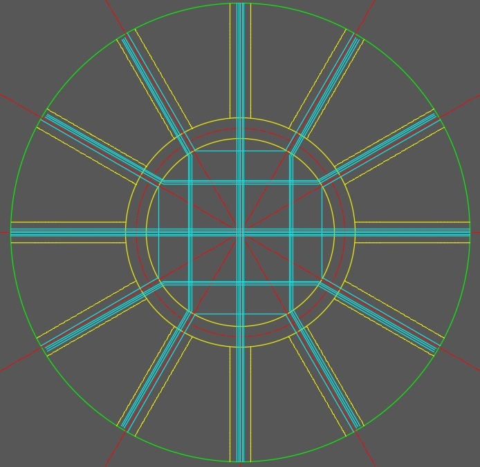
Oh. My. Goodness. I would cut off a pinky finger to switch places with you this week. I'll throw my hat in the ring. See my proposal below. I'm torn as to whether or not there should be a little hogging in the primary girder cables between columns. Maybe FEM can point you in the right direction in that regard.

Capture_2_fkgqk7.jpg


I like to debate structural engineering theory -- a lot. If I challenge you on something, know that I'm doing so because I respect your opinion enough to either change it or adopt it.
 
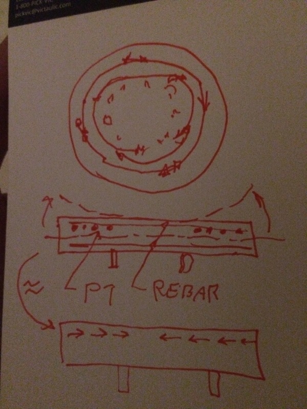
Another intersting consideration is that your circumferential PT should help to create your radial prestress by virtue of the circumferential PT in the slab always being above the centroid of your girders.

image_suusri.jpg


I like to debate structural engineering theory -- a lot. If I challenge you on something, know that I'm doing so because I respect your opinion enough to either change it or adopt it.
 
FullSizeRender_fiailp.jpg


KootK,

Thank you for always helping me out.

I think there definitely will be hogging @ center.

Actually I have almost same idea as yours except my secondary beams are not continuous as per sketch above with one cantilever & 10 m back span. Yours is better :). In your proposal, I understand how to design every individual secondary beam with core at the middle but since the core is shared by many beams, frankly I have no idea how to design & consider the combined effect & never done it before.

BTW, I am using 2D frame analysis software.

Thanks
 
No sweat. My wife's away on business so it's either this or spend time with my kids.

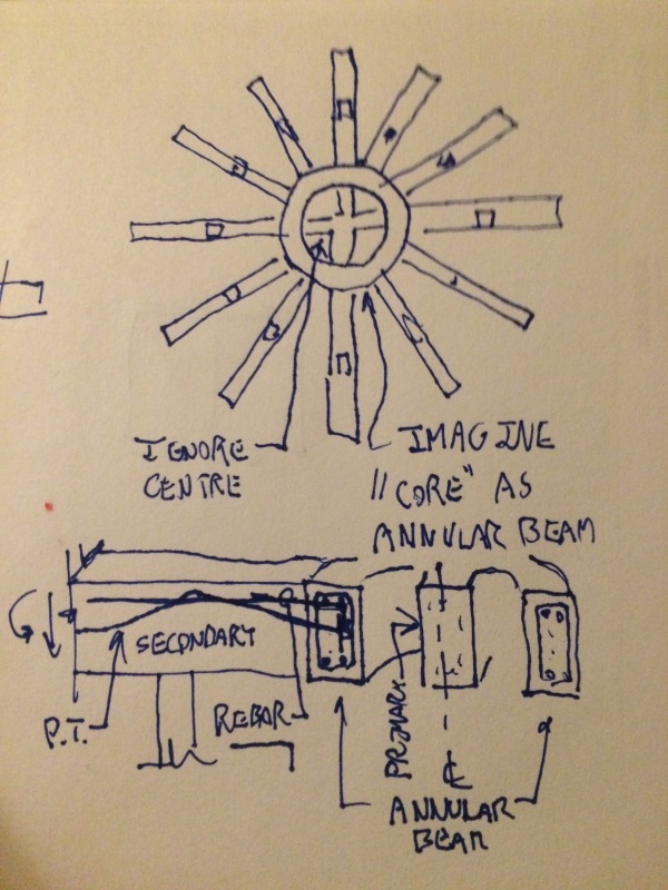
I'd conceptualize an annular beam within the core picking up load at the secondary beams and dropping it off at the primaries.

image_e2qbwr.jpg


I like to debate structural engineering theory -- a lot. If I challenge you on something, know that I'm doing so because I respect your opinion enough to either change it or adopt it.
 
Radial is not very good for this. There will be 6 layers of reinforcing and prestress at the centre. And then your slabs are radial as well.

2 parallel beams in orthogonal directions over the columns either side of the centre, beam across the ends at the outside edge the edge (they could follow the edge but will be easier to build and be more efficient if straight as shown)) and secondary beams if you want to reduce slab spans (possibly 2 in each direction but probably not needed with the straight edge beams), all parallel to the other beams. With those extra beams if would probably be possible to do the slabs as RC only.

This allows orthogonal prestress in both the slabs and the beams and a sensible centre zone where the top steel doesn't extend half the depth of the beams.

And you can get rid of the rest of the columns.

And this is actually buildable!

Image1_yfhhxx.jpg
 
Top marks to rapt, but i would stick with a pt slab at 12m spans and a orthogoal grid on the beams as suggest by rapt. Or add some extra beams in the ortho directions

"Programming today is a race between software engineers striving to build bigger and better idiot-proof programs, and the Universe trying to produce bigger and better idiots. So far, the Universe is winning."
 
@Struggle66: I agree with rowing, Rapt's solution is the most constructible so far. Curious: is this a one off slab or a repeating floor? Will the underside be concealed or exposed to view?

I like to debate structural engineering theory -- a lot. If I challenge you on something, know that I'm doing so because I respect your opinion enough to either change it or adopt it.
 
Struggle said:
Actually I have almost same idea as yours except my secondary beams are not continuous as per sketch above with one cantilever & 10 m back span

My secondary beams were also not continuous with respect to the PT. If you look closely, I was proposing to dead end the secondary beam cables just shy of centre, the same as you.

I like to debate structural engineering theory -- a lot. If I challenge you on something, know that I'm doing so because I respect your opinion enough to either change it or adopt it.
 
Rapt,

If there is an annular beam as KootK suggested only two layers of tendons & reinforcement will be crossing at the center. But anyway, I'd tried your proposed layout, before I went for radial layout. Now my radial beam depth is 600 mm at the tip of the cantilever & 1200 mm at the column. I think I am gonna need deeper beams in your layout as there are point loads from secondary beams at the tip of the cantilever & lesser beams which is not possible for my floor height.

Agree it is simple & buildable. I am gonna try add more beams in your layout.

KootK,

Glad to know I have same idea as you.:)

Thanks all.
 
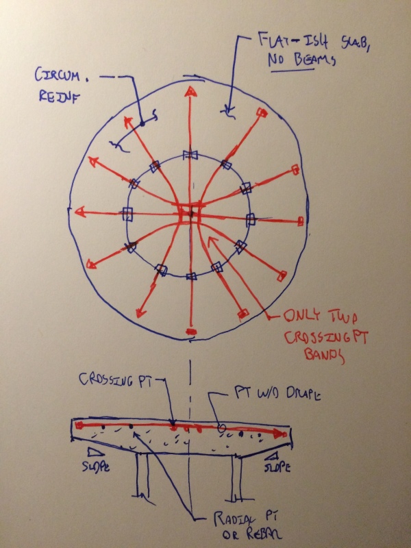
I can't help but think that there's an elegant, flat-ish plate option in here somewhere that would eliminate the beam formwork and minimize depth. Given the desire for a tapered profile, things might be able to be further simplified by eliminating the tendon drape altogether.

image_rvpl8r.jpg


I like to debate structural engineering theory -- a lot. If I challenge you on something, know that I'm doing so because I respect your opinion enough to either change it or adopt it.
 
Provide a wide girder over the columns and design it for torsion/arching action from the cantilevered beams (also useful for the lateral frame). Make the interior a 2-way flat slab (16") or waffle slab (24"). Redirect tendons to orthogonal directions on the interior slab - splay as desired.

circle_plan_bgf9aq.jpg


circle_section_fg8tz9.jpg
 
Struggle,

I doubt that you will be able to justify terminating a large number of cables "just shy of the centre" to avoid overlaps once you really look at it in detail (make sure the software you are using is allowing for the tension force offset requirements for shear (none of the FEM software allows for it as far as I know!)). You will be terminating a large amount of you prestress in an important tension zone and that is not a good idea!

I have 8 beams. you have 12. Make the 8 beams 50% wider!

You could do the whole thing as a flat plate (or flat slab with a large "drop panel" in the centre to about 4m past the ring of columns on my layout logic with column strips in both directions (support strips) on the column lines and around the edge and middle strips in both directions between. Definitely do not use the US one way banded/distributed logic!
 
struggle66 ,

I assume there is a lift core and stair core somewhere in this building! presumably at the centre? If so, radial beams do not work very well!

Also. it would make it a lot easier to make suggestions if we knew where it is in the floor plan as its location will have a major effect on the structural layout!
 
rapt,

Thanks

Rapt said:
[make sure the software you are using is allowing for the tension force offset requirements for shear (none of the FEM software allows for it as far as I know!/quote]

I am using RAPT software. Glad that you bring this up. I wanted to ask you & always wondering once I terminate a tendon in the somewhere in the beam span in RAPT, RAPT gives me a significant amount of rebar for shear. If you don't mind! Could you please tutor & explain me about "tension force offset requirements for shear?

I will look into your layout with more or wider beam.

Yes, you are right there are a few stair cases & lift walls making radial beams layout difficult.
 
Struggle66,

Part of the problem when we design concrete members is that we design reinforcement for flexure and then check shear separately, but they are not separate, shear adds extra flexural reinforcement requirements.

For reinforced concrete design, most design codes require that reinforcement be fully developed at least D past the point where it is required. This is to satisfy the logic of the truss analogy for shear. By normal strength calculation you will need less reinforcement at a point with lower moment D from the point where you are doing the calculations in the direction of reducing moment (top or bottom). But the code requires that the reinforcement supplied at D away is the same as that required at the point. The extra amount RAPT says flexural reinforcement required to satisfy shear.

The actual requirement is actually that the tension force REQUIRED at a point be supplied for a distance D past that point, not the amount of reinforcement supplied. So if you do not require all of the reinforcement supplied at a point, then you only have to extend the amount required at that point by D. Codes have simplified this to simply save to extend all of the reinforcement D past the point.

This distinction between reinforcement and its tension force is important when you look at PT as you obviously cannot extend the PT cable past the point where it terminates. But the requirement still applies to PT. So if a PT tendon is fully required at the point just before it terminates, the force supplied by that tendon at Ultimate must be replaced with normal reinforcement, fully developed back past the tendon and fully developed at least D past that point. If only 50% of the tendon capacity is being used, then 50% of the tension force needs to be replaced.

The only design code that explains this fully for all members Eurocode. The latest Australian commentary also has the same explanation and the next Australian code will be changed to define the requirements properly for both RC and PT members. RAPT follows the Eurocode logic on this for all codes for RC and PT members as none of the other codes explain how it should be treated for PT members and some don't explain it at all.
 
Trenno,

You do not normally base the nominated year on the starting year! And on past performance it will take another 10!
 
Status
Not open for further replies.

Part and Inventory Search

Sponsor