Continue to Site

Eng-Tips is the largest engineering community on the Internet

Intelligent Work Forums for Engineering Professionals

  • Congratulations SDETERS on being selected by the Eng-Tips community for having the most helpful posts in the forums last week. Way to Go!

PT Circular Floor 7

Status
Not open for further replies.

struggle66

Civil/Environmental
Jul 5, 2013
127
PT_Circular_Floor_k41zt8.png


Hi Good Day Everyone,

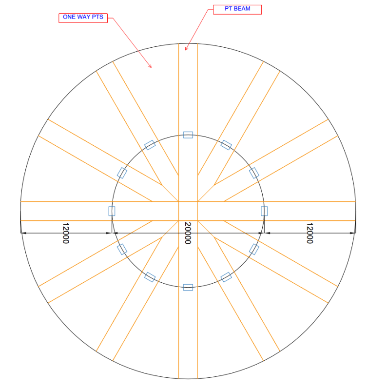
I've got to propose PT layout for above circular PT layout for a residential building with 12m cantilever on each side (Columns are only allowed on inner circle perimeter). I am thinking to propose as above but if that so except the rebar & tendon congestion @ the center of the circle, there will be a lot of pre-compression (P/A) due to PT & a lot beam design will share the section. It is my first time to encounter this kind of layout.

How should I approach, analysis & design? Thanks in advance for your help.

Thanks
 
Replies continue below

Recommended for you

Rapt said:
You will be terminating a large amount of you prestress in an important tension zone and that is not a good idea!

I agree with the logic of tension shift but not the statement above. In the case of the radial, secondary beams the PT is not terminated at an important tension zone. Rather, it is terminated at a simple support (annular beams) where the moment, and Bernoull flexural tension, would be zero. There's still a tension shift issue there that requires anchorage past the support face for the required tension. However, it would be easily satisfied by extending the PT into the annular beams and supplying some local top steel as I indicated in my sketches above.

I like to debate structural engineering theory -- a lot. If I challenge you on something, know that I'm doing so because I respect your opinion enough to either change it or adopt it.
 
rapt,

Thanks

I understand the logic of truss analogy for shear for conventional RC. Just forgot tension force in the tendons :).

So RAPT software will extend the reinforcement at a point by D based on the tension REQUIRED at that point (not user defined reinforcement we PROVIDED). Since the tendons are at higher level & the reinforcement RAPT provides to extend by D are at lower level, does RAPT take that difference in effective depth into consideration too?

I am asking this because in one of my project, structural consultant overdesigned a beam & added tendon for nothing (Even without the tendons the beam is ok). I had to check beam design for a reason & once I added in the tendon & terminated at 1/4 of the span, RAPT gave me a lot of reinforcement. & When I removed the tendons, those reinforcement disappeared. I may had misinterpreted the design. I will go see the beam design again.
 
Struggle

RAPT calculates the tension required at a point based on Mu / lever arm of all of the reinforcement and tendons at that point.

It then checks that the reinforcement and tendons at the next point provide sufficient tension. If not, extra reinforcement is added to the design layer to account for the difference.

depth is not involved as the tension does not have to be at the same depth at the 2 locations. It is not the moment capacity you have to provide at the offset location, only the amount of tension force.

If unsure, send the run to me.
 
Thanks rapt,

Really wise I have mentor like you & KootK.

 
rapt said:
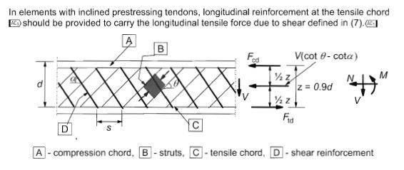
The only design code that explains this fully for all members Eurocode.

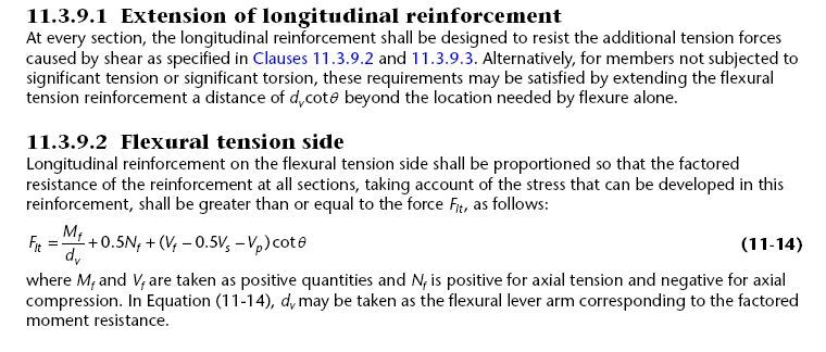
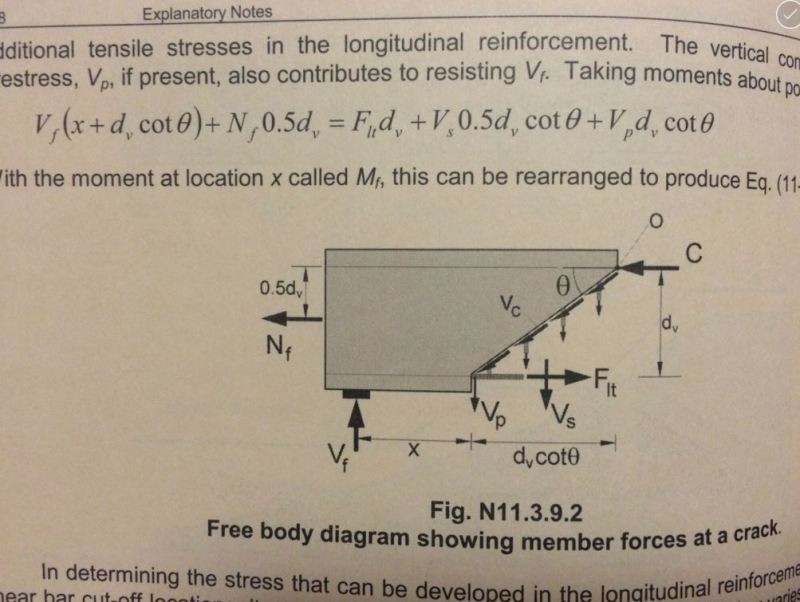
With the eurocode provisions governing this, is there more to it than the sections shown below? The Canadian code has an analogous provision and an associated commentary diagram (also below).

rapt said:
This distinction between reinforcement and its tension force is important when you look at PT as you obviously cannot extend the PT cable past the point where it terminates. But the requirement still applies to PT. So if a PT tendon is fully required at the point just before it terminates, the force supplied by that tendon at Ultimate must be replaced with normal reinforcement, fully developed back past the tendon and fully developed at least D past that point

Just to clarify, one could eliminate the need for the extra mild reinforcement by extending the PT beyond the theoretical cutoff point, correct? Similar to mild rebar cutoffs?

Eurocode

Capture02_lvcf7f.jpg

Capture03_fu7z6d.jpg


Canadian Code

Capture01_ftseer.jpg

Capture01_ywgyvv.jpg


I like to debate structural engineering theory -- a lot. If I challenge you on something, know that I'm doing so because I respect your opinion enough to either change it or adopt it.
 
Kootk

You have shown the EC section for sections requiring shear reinforcement. There is also a section on sections not requiring shear reinforcement and one in 9.2 on detailing. There is also another section in Beam Shear design showing what defined reinforcement can be considered to be active at a cross-section for shear due to the force offset requirements.

The Canadian code is not used widely outside Canada, though the shear provisions are widely read, and Struggle uses either BS or Eurocode as do many around the world.

For PT, the normal procedure is to define where the tendons terminate and then do the design. Yes, it would be possible to extend the tendons to cover the force discrepancy, but then the member would have to be redesigned to account for the change in the PT tendon extents and the force requirements will change. And quite often the tendons stop at a specific location for a reason.
For RC design, once the flexural design is done, you can normally just extend the reinforcement without having to redesign.
 
Status
Not open for further replies.

Part and Inventory Search

Sponsor