Eng-Tips is the largest engineering community on the Internet

Intelligent Work Forums for Engineering Professionals

  • Congratulations waross on being selected by the Tek-Tips community for having the most helpful posts in the forums last week. Way to Go!

Pump A discharge line merging downstream with pump B discharge line 1

Status
Not open for further replies.

unclebensrice

Petroleum
Oct 1, 2010
44
0
0
GB
Dear all,

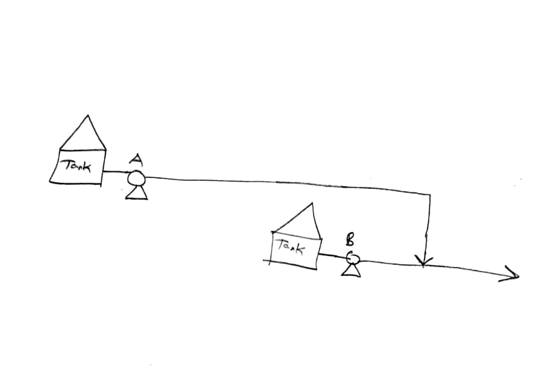
Whenever Pump B comes online, pressure on Pump A goes up and trips it. is there anything that can be done to resolve this? both pumps need to be working simultaneously.

thanks.

sketch_omtp9g.jpg
 
Replies continue below

Recommended for you

Having a long pipe between two pumps operating in parallel is a bad idea. One solution is as follows(without more data I can not check the feasibility):

1. Trim the pump A impeller to have less head.
2. Pump from Tank A to tank B by pump A. Introduce throttling valve if required in pump A discharge line..
3. Pump from tank B to final destination.

You need to check the pump capacities whether they are adequate.
But your pump B data seems in doubt. If it is rated for 290 ft only, how the pressure can shoot up to 190 psi ?


Engineers, think what we have done to the environment !
 
Goutam,

The advised SG of the fluid is 1.14. No idea what this fluid is but that will give you about 380 ft at pump A.

I think the system works Ok when both pumps are flowing, but when it's only pump A the pipe is clearly too big and hence the pump goes off the end of the curve. To stop that the site guys throttle pump A to reduce flow (but we don't know to what flow or discharge pressure). Then when pump B starts this increases the pressure and hence pump A flow reduces. Then the site guys need to run around opening it again. Several times a day by all accounts.

But we know very little about the system so don't even know if this is the same fluid.

And going into tank B would reduce overall flow to the capacity of pump B. At the moment it looks like they do get some benefit from running both pumps in parallel.


Remember - More details = better answers
Also: If you get a response it's polite to respond to it.
 
@LittleInch
My one point was that with 295 ft at pump B the pressure it can generate is only 145 PSI (SG 1.14). Assuming no flow from pump A the line pressure should be 145 PSI not 190 PSI.( Assuming no goof up in my calculation.)
Also they are getting only the flow from pump B at present running in parallel. They can not use tank A running in parallel. So they can use the pumps in isolation only. That is use pump A or B at a time.

Engineers, think what we have done to the environment !
 
Goutam - the story and the data keeps changing....

first Ben said it tripped, now he says it's some poor operator running between pumps adjusting valves that's the problem.

We have about 10% of the information to advise him but he won't give us it or doesn't know it.

Remember - More details = better answers
Also: If you get a response it's polite to respond to it.
 
Yep, looks like another 50 post saga starting up, slowly dragging out info' bit by bit that will never end until everyone including the OP gives it away.
Given the necessary data it's a 5 minute exercise to sort it out, let's see what happens.

It is a capital mistake to theorise before one has data. Insensibly one begins to twist facts to suit theories, instead of theories to suit facts. (Sherlock Holmes - A Scandal in Bohemia.)
 
Status
Not open for further replies.
Back
Top