Continue to Site

Eng-Tips is the largest engineering community on the Internet

Intelligent Work Forums for Engineering Professionals

  • Congratulations KootK on being selected by the Eng-Tips community for having the most helpful posts in the forums last week. Way to Go!

Pump discharge line size calculation 4

Status
Not open for further replies.

Asisraja D

Mechanical
Jan 3, 2024
149
Hello professionals
Thank you for going to help me.
We have pump with capacity of
180 m3/hr , head = 45 meters.
Pump nozzle size is 100mm x 80mm
But in our plant we already installed piping for suction with 150mm inlet piping and discharge with 250mm outlet piping to the plant
(This is cooling water supply and return line both are the same size as 250mm)
So I calculated the velocity method (Q=A X V) with the known pipe size and flow rate I get 1m/s.

Few more details for your reference:

1.Pipe material is Mild steel "C" class pipe
2.Pipe length from cooling tower sump to plant supply (250mm) EOL is 80 meters.
3.Pipe length from Main header to sub-header supply (200mm) EOL is 30 meters.

My doubt is all about discharge nozzle size with discharge piping size.
Did we take wrong piping size for discharge line?
Is there any rule of thumb or design considerations for pump piping as applicable to liquid flow.

I have attached my hand sketch for more clarity.
 
 https://files.engineering.com/getfile.aspx?folder=66792b5e-06e5-4dfa-9d69-a9c4177dbaca&file=IMG_20240223_114207.jpg
Replies continue below

Recommended for you

Sorry to interrupt you all again. Today I checked my pump name plate it has Q (rated) = 180 m3/hr
Max 284 m3/hr.
Same as head (rated) 45 Mtr but max 65 MTR.

What does it mean ? If anyone have seen this picture please explain me a Little bit.

I attached the nameplate image.
 
 https://files.engineering.com/getfile.aspx?folder=fb38f4a3-61b2-4f2f-b0c4-ea7eb6082905&file=IMG_20240224_145907.jpg
The data on the plate shows that the rated flow and head are 180 cubic metres per hour and 45m, respectively.

The max figures are the flow and head that the pump can reach, but not at the same time.

If the head goes up, the flow comes down and likewise, if the flow goes up, the head comes down. The performance details will also tell you the BEP, best efficiency point for the pump. The BEP should be at the rated point for the pump. So 80% efficiency at Q=180 and H=45. If you run the pump with flow and pressure away from the BEP, the efficiency will be less than 80%.
 
FluidPowerUser sir
The max figures are the flow and head that the pump can reach, but not at the same time.

So there is some possibility to achieve that max figures? If so what will affect them to achieve that max figures like head loss or any other parameters like improper piping size.

This is really interesting and new for me sir.[pre][/pre]
 
Those numbers could be two things.

1, the max flow and head available with the biggest impellor that will fit in that pump.

Or

2 The max flow at the end of the curve. So the head would be lower than 45.
Maxhead is probably no flow / shut in head.

If the resistance to flow in your system is lower than 45m at 180 m3/ hr then the flow will increase until the frictional l and other losses equa, the head out out by the pump.

This could be because of bigger pipe, shorter ,length, less valves a d other fittings than calculated, opening up control valves, less resistance to flow in any item


Remember - More details = better answers
Also: If you get a response it's polite to respond to it.
 
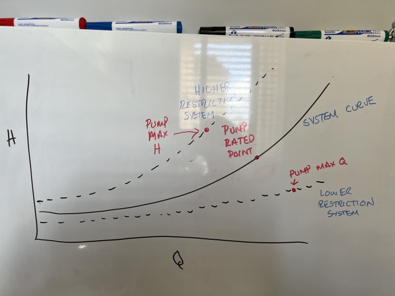
As mentioned before a centrifugal pump will change its output depending on the conditions placed in the discharge line.

The pump rating for H and Q are at the best efficiency point.

If you add more restrictions in the line, the pressure will go up, but the flow will be lower. Likewise, if you reduce the restriction in the line, the pressure will go down and flow will increase.
IMG_2407_visplz.jpg


The max values on the pump plate are telling you the max that the pump will do, irrespective of how low or high the system’s restriction is.
 
The chart is very useful, but max head will be at zero flow in most instances.

The point marked pump max head is just higher than the rated head. IMHO.

Remember - More details = better answers
Also: If you get a response it's polite to respond to it.
 
LittleInch sir If the resistance to flow in your system is lower than 45m at 180 m3/ hr then the flow will increase until the frictional l and other losses equa, the head out out by the pump.

So this is just a guess work because our BEP
denotes 180 m3/hr as rated. If so the capacity of the pump is more than denoted value like a straight line without any restriction like bends, valves, change of pipe section, elevation etc.

Yes if I don't have any restriction to the flow absolutely I can achieve that MAX figure.
 
FluidPowerUser sir If you add more restrictions in the line, the pressure will go up, but the flow will be lower. Likewise, if you reduce the restriction in the line, the pressure will go down and flow will increase.

The max values on the pump plate are telling you the max that the pump will do, irrespective of how low or high the system’s restriction is.

So I must have reduce the restrictions in my piping (straight pipe without any bends or fitting etc) to get more flow even if I want to get that Max flow rate, yes it is achievable.

 
I can’t agree with that point, but I’m not being argumentative.

We don’t know if the impeller is unshrouded, single shrouded or double shrouded. Also, the volute is designed around the impeller to match the head and flow performance. If you change the impeller in the volute, the performance of the pump will change dramatically. It’s the OD of the impeller that determines the pressure that the pump can produce as the flow is generated by the vanes of the impeller and the fluid is flung outwards and collected in the volute.

Zero flow on a centrifugal pump will result in zero pressure as pressure is simply the resistance of flow. It will also not cool the pump seal, so what would be the point of having an unachievable performance point on the plate?

That’s just my opinion based on experience of pump design.
 
I did say most pumps but shut in head/ no flow is not zero head. There is internal re circulation. It is normally the highest pressure the pump will generate.

Shut in head is quoted to make sure the piping etc can withstand the pressure if the flow is stopped/ valve closed somewhere downstream.

Remember - More details = better answers
Also: If you get a response it's polite to respond to it.
 
OK then….

Just semantics then.

In response to the last question from the OP.

Normally, you’d design the system to get what you need in terms of heat transfer and operating performance, then calculate the flow and head you need, then select a pump that can achieve the desired output.

In this case, you effectively have 45m of head or 4.5 BAR to play with and you need to make sure there is enough left at the end of the line to keep the pump out of cavitation. Just having a flooded suction might not be enough. Your pump needs 4.5m of head at the inlet.
 
Errrr NPSH is absolute head.

And no one has stated what this is.

Pumps deliver differential head so add that to the inlet pressure.

But I've got lost where this thread is going...

Remember - More details = better answers
Also: If you get a response it's polite to respond to it.
 
The thread is jumping all over the place from pumps to pressure drop to inlet pressure.

NPSH required is stated as 4.2m

That’s 4.2 metres of absolute pressure or 420 millibars minus the vapour pressure of the water and we don’t know that. So I was just making reference to it as it needs to be calculated by the OP.
 
FluidPowerUser sir Just having a flooded suction might not be enough. Your pump needs 4.5m of head at the inlet.

But I have calculated our NPSHA it is just 3.12 MTR.

I referred this site for my calculations:

I have attached the image please review it and if any error I my calculations guide me to correct them. Thank you sir.
 
That pipe entrance loss looks looks very high.

How was it calculated?

But then you haven't allowed much for your strainer. Is this a very big mesh?

Remember - More details = better answers
Also: If you get a response it's polite to respond to it.
 
LittleInch sir I have attached the pressure drop calculation and we have two outlet from sump
Should I need to add 0.63 X 2 = 1.26.

Yes. Strainer size is 12" but I don't know the mesh dia size.

 
 https://files.engineering.com/getfile.aspx?folder=cabbd0aa-b189-4a1e-8d38-d4fa2fad77e2&file=Screenshot_2024-02-25-22-08-32-717_com.android.chrome.jpg
Read it properly.

It says 0.63 milli bar, not bar,

So basically 0.00063 bar or negligible.

I would allow 2m for the strainer basket.

Remember - More details = better answers
Also: If you get a response it's polite to respond to it.
 
LittleInch sir
I have corrected my calculations.

NPSHA= (Absolute pressure head - vapour pressure
+ static head - pump suction line losses)

NPSHA = (10.33-0.238+1.8-2.51)
= 9.3 meters

But our pump needs 4.2 NPSHR

If so I have enough head to this system.

Can you please review this sir.
 
Status
Not open for further replies.

Part and Inventory Search

Sponsor