Continue to Site

Eng-Tips is the largest engineering community on the Internet

Intelligent Work Forums for Engineering Professionals

  • Congratulations KootK on being selected by the Eng-Tips community for having the most helpful posts in the forums last week. Way to Go!

Question about Datum Reference frame(DRF) 5

Status
Not open for further replies.

alone_dancer

Mechanical
Dec 8, 2020
19
Hello,
I have a question about the DRF. How to define it for the actual part?
Is the understanding of the two DRFs on the left side of the figure below correct?
My doubts are mainly about the origin and direction of the coordinate system.
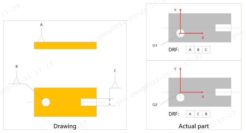
DRF_x3qg23.png


Thank you.
 
Replies continue below

Recommended for you

Would be VERY helpful for you to understand the concept and also for us to help the discussion if some relationship between A, B and C are shown.
 
Both of them look correct to me. You have me a little confused by saying the two DRFs on the left side. I see two DRFs on the right.

John Acosta, GDTP Senior Level
 
I think you're asking about some accidental offset -- if the slot is not directly across from the hole.
The lower picture on the right has the correct x/y coordinates for that arrangement of datum references (because the slot locates the horizontal before the hole is engaged).
But the upper picture isn't correct -- If the hole is the secondary datum feature, then you indeed have the origin of the x/y at the correct location. But since the slot only controls rotation, the two red lines would be rotated counterclockwise a little. (Or, to say it better, you can keep the red lines there, but the entire gray part would be rotated clockwise a little -- see pmarc's picture below.)

The best way to think about it is to envision a fixture (datum feature simulators) that would engage A, B, and C. The block that slides into that slot (for the upper picture) is always directly in line with the hole's axis. Even if the slot is shifted up, the simulator still slides into the slot while in line with the hole's axis.

John-Paul Belanger
Certified Sr. GD&T Professional
Geometric Learning Systems
 
alone_dancer,

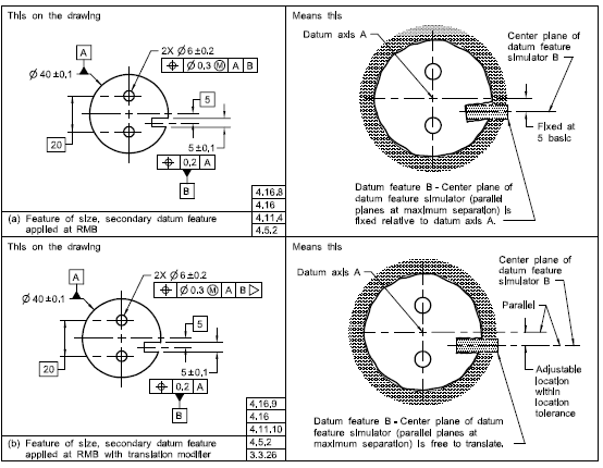
This may not be the exact scenario but it looks close to the question you're asking. This is from Section 4 of ASME Y14.5-2009 standard.


Capture_ucvnyx.png


John Acosta, GDTP Senior Level
 
@Greenimi @Powerhound
Thanks for your response.
Yes, it would be VERY helpful if there are some geometric tolerance between A, B and C are shown.
Sorry for confusing.
What I want to say is the determination of the actual DRF under the two DRF (ABC/ACB) annotations for the drawings on the left and the actual parts on the right.
Assuming the features A, B and C of the actual part on the right is ideal, only the center of slot C and hole B has some offset.
 

Belanger,
Really appreciate your detailed explanation and great advice.
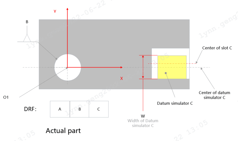
I have a question about the fixture you mentioned. The fixture (datum feature simulator) will be like the yellow part shown in the figure, and 'W' (width of of Datum simulator C) is adjustable so that it aligns with the hole at the center while matching the slot. Is it correct?
DRF-2_d7ahsh.png
 
powerhound said:
This may not be the exact scenario but it looks close to the question you're asking. This is from Section 4 of ASME Y14.5-2009 standard.
Thanks for the example.
It is also what I want. I'll study it.
 
The yellow simulator will be adjustable in width (because there's no "M" after the datum reference in the feature control frame). But its center will need to stay in line with the datum B axis.

John-Paul Belanger
Certified Sr. GD&T Professional
Geometric Learning Systems
 
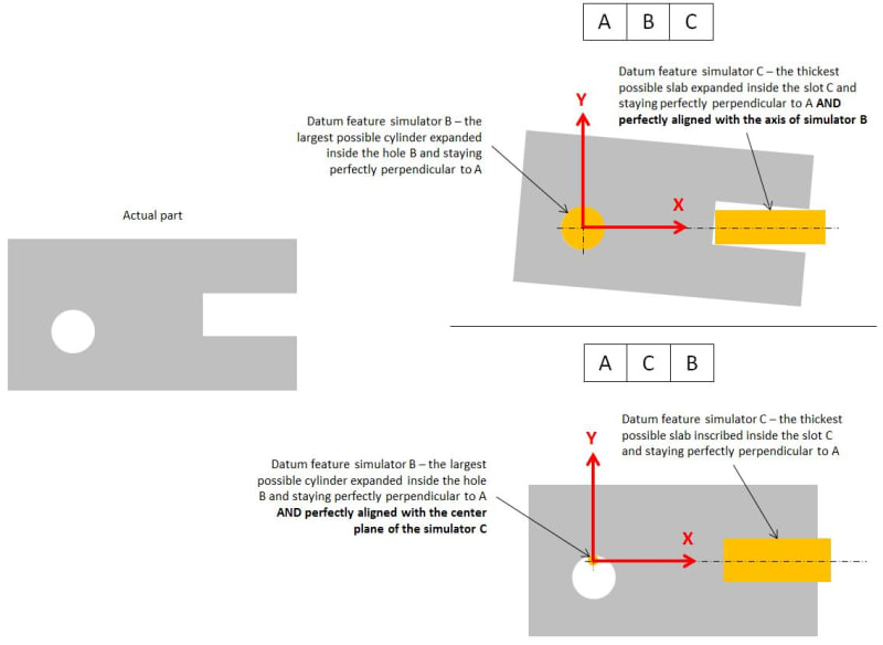
I think this is how the two alignments for the part in question should look like:

different_alignments_jtvo5e.jpg
 
Belanger said:
The yellow simulator will be adjustable in width (because there's no "M" after the datum reference in the feature control frame). But its center will need to stay in line with the datum B axis.
Got it. Many thanks.
 
pmarc said:
I think this is how the two alignments for the part in question should look like:

Totally understand. Thank you very much for your detailed explanation.

So an important thing is that the position tolerance of the tertiary datum feature relative to the primary and secondary datum feature should be defined.
 
Pmarc,

Am I correct in saying that your shown cases and solutions are valid for 2009/2018 and not valid per 1994?
 
greenimi,

Yes, the shown cases are valid if 2009 or 2018 is used.

As for 1994, I would say that the information contained in the standard may be deemed contradictory. On one hand, it says in para. 4.5.3.(d) that the tertiary TGC "must be oriented in relation to both the primary and the secondary datum" - notice that there is no mention of location relationship. On the other hand, the associated figure 4-15 shows the center plane of the TGC of the tertiary datum width C aligned with secondary datum axis B. Is it aligned just because the actual geometry used in the figure is such that the TGC of C happens to be perfectly aligned with datum axis B or because they applied locational constraint between TGCs of C and B, I am not able to tell.

What I know, however, is that in the math standard supporting the 1994 - Y14.5.1M-1994 - there is a figure (4-2) clearly showing that the secondary and tertiary TGCs are only basically oriented to each other. So this would actually support the statement you made in the question.
 
pmarc,
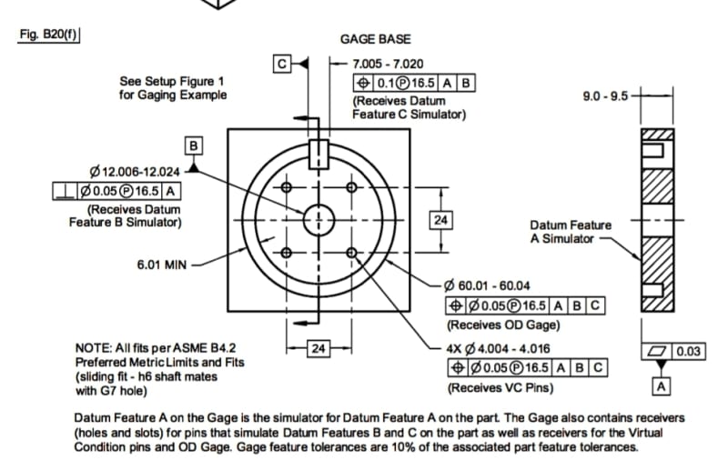
Interesting point about the difference in datum feature simulator requirements - mutual basic location and orientation (2009 and on) VS basic mutual orientation only (?)(1994). As you mentioned fig 4-2 in the 1994 version of the math standard seems to support the orientation only version, but how did the gages and fixtures standard address this? Admittedly I am barely familiar with Y14.43 but my copy of the 2003 version (supporting the '94 tolerancing standard) shows figures such as B20 for a part that bears similarity to the one in fig. 4-2 of the math standard, and the receiver for the tertiary datum simulator key is shown toleranced for centering per gage tolerances to the receiver of the shaft that simulates datum bore B. There is no indication that center plane to axis offset may be allowed to accommodate an as-produced part... Am I missing something within Y14.43?

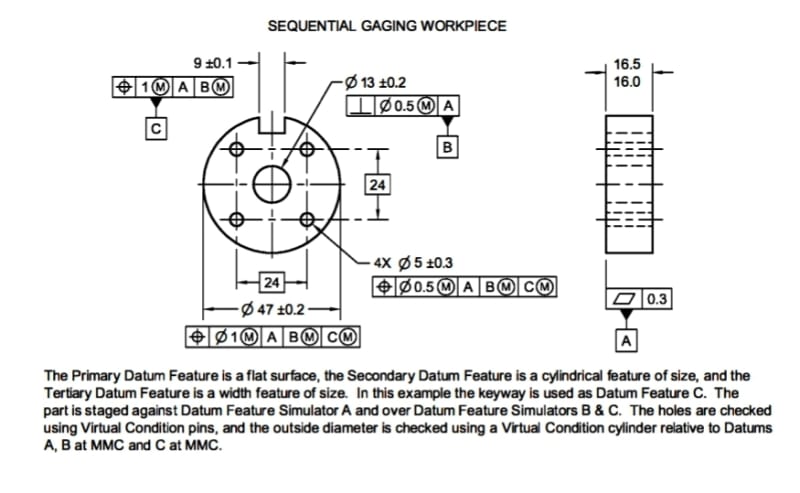
Screenshot_20220624-152332_Drive_pl1tor.jpg


Screenshot_20220624-152306_Drive_hhbt2n.jpg
 
No, I don't think you are missing something within Y14.43. Even in para. 3.2.2.(e).3 they say that the tab simulator is to be oriented and located relative to the simulators of higher precedence.

The only exceptions to this requirement (applicable for cylindrical datum features of size, though) are defined in para. 3.2.2.(g).

So it seems like different subcommittees decided to make their own call on the topic.
 
pmarc said:
So it seems like different subcommittees decided to make their own call on the topic.

I find it interesting that Jim Meadows seems not to be very happy about the rulling, even he already followed it in 2003 version. (I posted his replay --copied from eng-tips-- before, so I'm sorry for reposting).
Don't you guys find it strange? So, I am complaining about changing the rules but in my own subcommittee's standard I am already abiding to the "new rule" that I am complaining about.
Or maybe I am missreading his emails and his intentions.


Also, since I am watching pmarc's posts, I want to say that I like your "unnecessary distraction" about diamond shape pins (2003)

pmarc : I believe the cylindrical vs. diamond-shaped pin topic is an unnecessary distraction. The pin should always be cylindrical to match the Y14.5 theory. But the important part is that in the 2003 version of Y14.43 the pin C is sliding, whereas in the 2011 it is fixed at basic distance relative to the pin B (in order to make it sliding the translation modified would have to be applied for C on the drawing). This is basically a consequence of the change that was made from Y14.5M-1994 to Y14.5-2009 in the rules for mutual relationship between TGCs/datum feature simulators.


Here is what James Meadows had to say: "This is the result of a long drawn out fight between individuals and committees. It's known as the "tertiary datum problem". Some of us said (as it currently says in the Y14.43 standard) that since the tertiary datum feature of size is only to give angular orientation to measurements taken from the secondary location datum axis (of a hole or shaft) that the datum feature simulator (real gage or fixture element) and the TGC (imaginary datum feature simulator) should translate (move) toward or away from the secondary simulator. Others said that both simulators should be represented as stationary, separated by their basic dimension, as is currently done for pattern datums. The stationary folks won the vote.

Then some of us pointed out that the result of this vote is that we aren't really measuring distance from the secondary hole or shaft, but are really measuring distance from both the secondary and tertiary datum features of size. What are we supposed to do when we want to actually have the secondary locate and the tertiary give us an angle of measurement? They came up with the translation modifier. It says that the tertiary (or sometimes secondary) datum feature it is attached to can be represented by a simulator that moves toward or away from the secondary (or sometimes primary) datum feature that precedes it in the feature control frame. That way the tertiary datum feature of size only gives orientation to the measurements.

It's a mess created to solve a problem that rarely existed. But the faction got what it wanted and that was a default rule that all datum feature simulators (real) or true geometric counterparts (imaginary) are stationary and separated by their basic dimensions (unless the translation modifier is used).

Since you didn't mention the planar datum features shown with a profile tolerance that can be referenced at MMC and represented at their virtual condition distances/sizes or the RFS ones that can grow from their basic dimensions until they contact the part, I won't either.

Things have gotten out of control, but there is no stopping this runaway train."

Thanks Jim
 
pmarc and greenimi,
Thank you for this input.
So apparently, it used to be a gray area  but now hopefully, all the related standards are in agreement about basic orientation AND location between TGCs / datum feature simulators, with some exceptions (although I don't have access to the mathematical definition standard to check if fig. 4-2 and the associated text were corrected. Were they?).

A follow-up question: does the ISO GPS standards treat the topic similarly? I.e, requiring spacing and orientation between datum simulators according to the TEDs?
 
greenimi,
I really don't want to start the whole conversation about the tertiary datum problem again, but to me - based on what is shown and stated in Y14.43-2203 - it almost seems like according to the proponents of the "orientation-only-constrained-TGCs" approach, the problem applied to the |cylindrical datum feature|cylindrical feature| scenarios only. Notice that the figure in Y14.43-2003 showing the sliding diamond pin as tertiary datum feature simulator (fig. B10) keeps the width of the pin centered on the secondary datum axis - this means it was not their intention to release the tangential translational degree of freedom of the diamond pin width with respect to the secondary simulator.

Burunduk,
Yes, the 2019 version of Y14.5.1 (that supports Y14.5-2009) has actually two figures - one showing the default condition in which the tertiary datum slot simulator is oriented and located with respect to the axis of the secondary datum feature simulator; second showing the configuration of the datum feature simulators when the translation modifier has been applied to the datum feature C reference in the position tolerance for the pattern of two holes. In this second case, the figure is similar to fig. 4-2 in Y14.5.1M-1994.

In ISO the approach is currently the same as was in ASME prior to 2009. However, based on my knowledge, they are planning to change the default rule to make it the same as has been in ASME since 2009.
 
Ugh...I'm late to return to this thread and after reading through the new posts this I see that, once again I didn't look closely enough at the OP. I was seeing a different question as evidenced by my snip that I posted later in the thread. I rescind my initial statement where I said they both looked correct.

John Acosta, GDTP Senior Level
 
Status
Not open for further replies.

Part and Inventory Search

Sponsor