Continue to Site

Eng-Tips is the largest engineering community on the Internet

Intelligent Work Forums for Engineering Professionals

  • Congratulations KootK on being selected by the Eng-Tips community for having the most helpful posts in the forums last week. Way to Go!

Question on basic dim/ Datum Scheme

Status
Not open for further replies.

MechEng1744

Mechanical
Jul 21, 2020
7
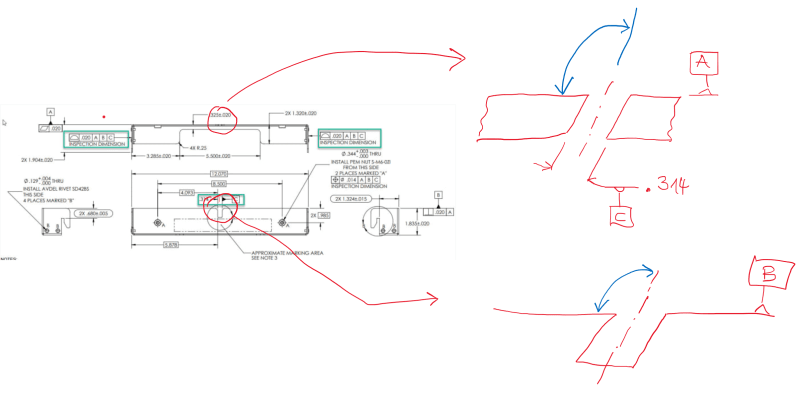
Another engineer made drawings at our company, and our inspection group is questioning this practice. Do all basic DIM HAVE to come from datums? Is this a valid scheme? If you can point me somewhere in y14.5 that would be helpful. I have a feeling this is legal, but I cant find out how... Thanks!

2020-07-21_9-46-42_m5gq6o.jpg
 
Replies continue below

Recommended for you

mfgenggear,

Where you place the datum feature flag is important. It can mean the center or just one face.

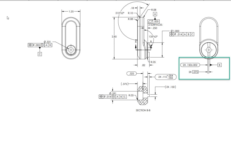
Flatness control is correct, but it does not control the relationship between the 2 surfaces. I would think the engineer should want to control the coplanarity. Since flatness only controls the form (coplanarity is a locational relationship). Both surfaces could be .005 or less flat (and pass inspections), but they could be offset from each other, let's say 1 in apart. And the part would still pass because you are only verifying the flatness. I hope this makes sense.

And the same applies to the 2 tabs. Just because they are shown inline on the drawing, it does not mean they will be coincident when manufactured. A positional callout without any datum reference should be used. Or you could remove "2X", keep the size tolerance, add the <CF> modifier (no need for a position callout as there would be only 1 continuous feature of size).
 
MechEng1744,

Datum feature C should have orientation callout wrt A and B. Without it, the definition is not complete. You may get unwanted parts, but you can't reject them if there is no callout.

Yes, datum C is the center plane of the feature. And yes, both profile callouts are correct.
 
Tarator, I hadn't noticed that until you point it out, but I do see your point there. Datum C is controlled and defined by the width of the feature, but there is nothing controlling it to A or B, so theoretically, those two features could be say 4 degrees off of A and B and it would be okay per current print. If i have to touch the drawing again, i will update.
 
MechEng1744,

Would you want to receive a part like this from your manufacturer?

1_kiywlt.png
 
Tarator
quote"Flatness control is correct, but it does not control the relationship between the 2 surfaces"

the drawing does say 2 surfaces under flatness

Quote "Both surfaces could be .005 or less flat (and pass inspections), but they could be offset from each other, let's say 1 in apart. And the part would still pass because you are only verifying the flatness. I hope this makes sense.

Tarator agreed
I instinctively would have manufactured them coplanar, I see the light
2 ways to do this is control or to tighten the dimension
ASME 2009 para 8..4.1.1 & fig 4-23
 
Status
Not open for further replies.

Part and Inventory Search

Sponsor