Continue to Site

Eng-Tips is the largest engineering community on the Internet

Intelligent Work Forums for Engineering Professionals

  • Congratulations LittleInch on being selected by the Eng-Tips community for having the most helpful posts in the forums last week. Way to Go!

Question overwriting default UOS

Status
Not open for further replies.

Kedu

Mechanical
May 9, 2017
193
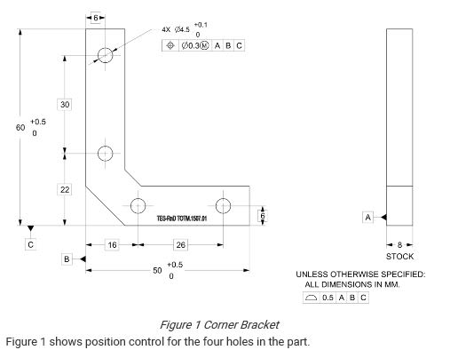
Is the sentence shown below correct? Should I understand that the holes are located by both (position and default profile) and the more stringent one takes precedence??

What the holes definition has to do with the unless otherwise specified note? I do not know I understand that. Thanks.


""""In Figure 1, the profile control in the note “UNLESS OTHERWISE SPECIFIED” confines the limits of the deviation permitted for the holes. When the selection of datums in FCF is partial, all requirements must be met (and determined by the more stringent one)!!!""""


HMM_1_-_Copy_yoahaz.jpg


HMM_2_-_Copy_pn50lf.jpg
 
Replies continue below

Recommended for you

The general profile note says "unless otherwise specified." The holes are clearly given tolerances that are "otherwise specified" (for size, form, orientation, and location -- the four main things).
So I don't understand the bit about datums in the FCF being partial.

John-Paul Belanger
Certified Sr. GD&T Professional
Geometric Learning Systems
 
I'm with JP, how do you determine if the datums are "partial"?

Certified Sr. GD&T Professional
 
By the way, what means "partial" datum ?
Should we understand that "partial" means that not all the degrees of freedom are locked?

I do not think that it is a standardized definition of partial in Y14.5.
Maybe it is in ISO, but I am not into ISO world (don't have enough knowledge)


I would also add that even if there was no position tolerance at all for the holes or the datums for position weren't specified, I don't see how the default profile could locate or orient them; since the diameters of the holes are not basic, but toleranced directly, I doubt that profile tolerance can be applied. The profile tolerance zone for the hole features is undefined. Anyone else thinks the same/differently?
 
I'm sorry, but someone needs general and GDT tolerancing and dimensioning training.

Certified Sr. GD&T Professional
 
mkcski, are you referring to the authors of this figure and written material? Judging by the logo that appears on the part drawing, it appears to belong to a company called "Tes-Rnd". A quick search on Google revealed that it is actually a company that provides GDT training which makes it all the more peculiar.
 
Maybe it's a case study for what NOT do that is used in one of their GDT courses.

Certified Sr. GD&T Professional
 
mkcski,
Maybe your last comment was tongue in cheek, but to be serious - I don't see any fundamental errors with the dimensioning and tolerancing on the drawing itself. It is the explanatory notes that accompany it which I find highly questionable.
 
Yes, it was tongue in cheek. I understand the drawing is not totally "bogus". But in this case, the note is a major component of the dimensioning schema that will alter the interpretation.

Certified Sr. GD&T Professional
 
Status
Not open for further replies.

Part and Inventory Search

Sponsor