Kevin G
Mechanical
- Oct 16, 2020
- 2
Hi Everyone,
I have a question regarding how flatness should be check on multiple datum planes.
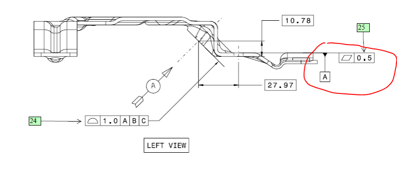
Side Section View
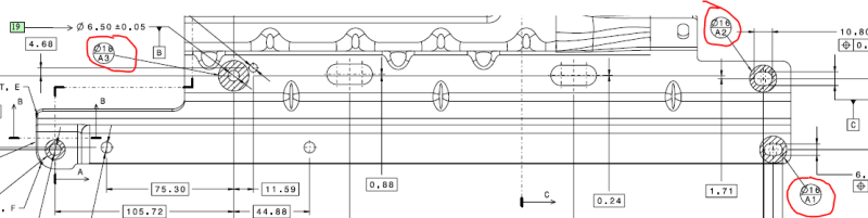
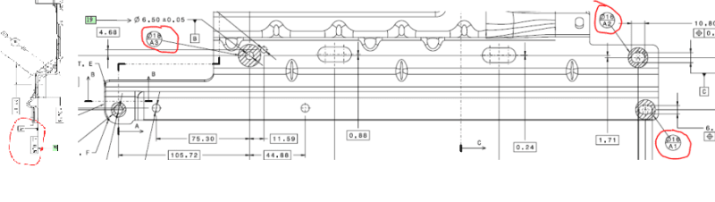
Top View
Would I check flatness of these areas locally excluding each other datum?
Or are they checked together. For example would I put the part on the checking fixture unclamped and slide a feeler under each Datum net pad area?
Or are the areas in between and around each datum considered in the flatness call out?
Thank you,
I have a question regarding how flatness should be check on multiple datum planes.
Side Section View
Top View
Would I check flatness of these areas locally excluding each other datum?
Or are they checked together. For example would I put the part on the checking fixture unclamped and slide a feeler under each Datum net pad area?
Or are the areas in between and around each datum considered in the flatness call out?
Thank you,
")