Continue to Site

Eng-Tips is the largest engineering community on the Internet

Intelligent Work Forums for Engineering Professionals

  • Congratulations KootK on being selected by the Eng-Tips community for having the most helpful posts in the forums last week. Way to Go!

Question relating to Profile of Surface that Tie into BASIC angles

Status
Not open for further replies.

brandnew1

Aerospace
Apr 9, 2010
73
Hi all,

When it comes to profile of surfaces i understand it to be a form and location tolerance of plus or minus half the value given.

The attached image reflects a profile of surface to datum a and b of .005 which i believe it gives tolerances of +/-.0025 for all BASIC dimensions called out.

However my question relates to tolerances when it comes to Angles. Examples i have seen when it comes to profile of surfaces all seem to just show theoretically perfect lines at a specific angle with a spacing of half the profile value. But im completing a PPAP for the customer and i need to put the upper and lower limit.

Can someone give some clarification regarding the attached pdf.

To reiterate, my understanding of profile of surface gives a plus or minus tolerance of .0025 (attached pdf) for all the BASIC dimensions (even the intersecting points) but angle wise i'm not so sure about. (i figure if the .175 and 1.985 BASICS are within +/-.0025 then it really isn't too critical - but i would like to see if there is a more solid answer).

P.S. i'm basing this question also based on another thread which the individual indicated, "Option 2 is to apply GD&T specifications to control the outline. A profile tolerance of 1mm allows ±0.5mm of wobble along the edge, making it equivalent to a ±0.3° tolerance, but it will not be as expensive. This is precisely the situation where GD&T works." - [URL unfurl="true"]https://www.eng-tips.com/viewthread.cfm?qid=284803[/url]

Thank you
 
Replies continue below

Recommended for you

brandnew1,

What standard are you working to? Is it ASME Y14.5?

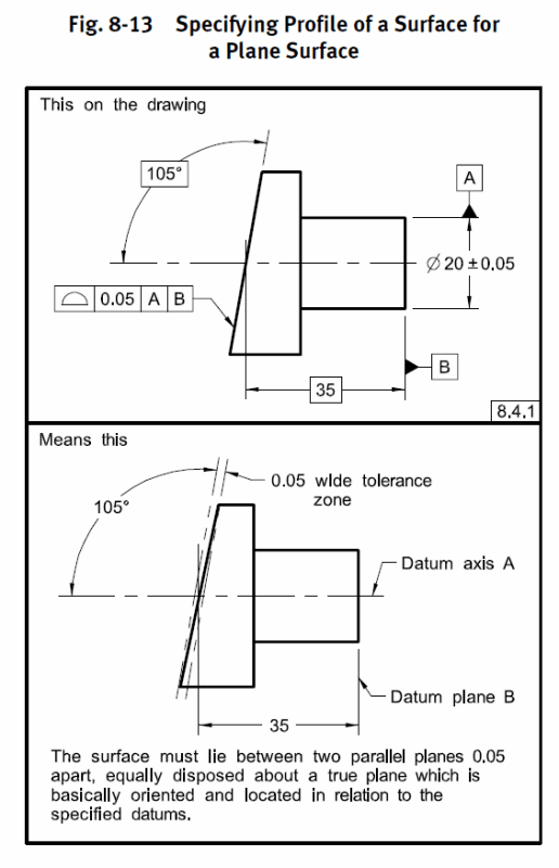
Depending on the datum features specified and modifiers (ie: dynamic profile modifier) profile has the ability to control all elements of size, form, location, and orientation. A bilateral profile tolerance is equally disposed (unilateral/unequally disposed are possible as well but bilateral is the default) about the true profile defined with basic dimensions, located and oriented to the specified DRF.

See below for an example for an inclined (angled) planar feature, assuming you are going by Y14.5 - though the story for ISO is not too dissimilar.

fig_8-13_fsjht7.png
 
brandnew1,

Basic dimensions should not be reported in the first place therefore there is no need to convert them to any other values. All that matters is if the toleranced surface lies within the specified profile tolerance zone or not.
 
Thank you chez311,

Yes this customer drawing is based off the ASME Y14.5-2009 standard.

pmarc,

Customer has a specific requirement for PPAP's, "All features on the drawing including basic dimensions shall be ballooned and listed on the Dimensional results report. Record the actual value of the basic dimension as a dimensional result as appropriate".

So given this, can it just be verified that the tolerances given for all the BASIC dimensions found in the attached pdf (OP) is +/-.0025 (other than the angles).

thank you
 
brandnew1 said:
So given this, can it just be verified that the tolerances given for all the BASIC dimensions found in the attached pdf (OP) is +/-.0025 (other than the angles).

Short answer is no. For example, no matter what the customer requirement says and requires, basic .175 has no tolerance because it defines the center of the true contour of the dia. 1.525 surface / center of the profile tolerance zone.
 
Reporting of profile tolerances can be tough as there is no way to output a single number like people would like to see on an inspection report.

Tolerances are not applied directly to the BASIC dimensions. Basic dimensions are by definition perfect, for a profile tolerance this establishes your true profile. The profile tolerance in this case establishes a tolerance zone equally disposed about the true profile by the amount shown in the feature control frame (the true profile being the ideal/perfect feature of basic size/form as well as location/orientation relative to your datum features). Your feature must simply fall within this tolerance zone as pmarc noted.

Your customer's PPAP documentation shows a lack of understanding of GDnT. There is no actual value of a basic dimension.
 
Trying to save pmarc from typing:):)


" I also agree with you that profile "needs some numbers, some pictures and some type of explanation to be properly conveyed for clear understanding by the person interpreting the information", but I do not agree that the single number is useless - it at least allows to immediately assess whether the actual surface conforms to the drawing requirement or not, and therefore if some additional actions need to be taken at all.

Y14.45 will have it all. It will define ways to require the measured profile data to be reported just as a single number, or as a single number with additional information, such as pictures, plots, etc."


In this case I would say Y14.45 is mostly (not only) about clarification.

One of the main goals of Y14.45 is to create a direct link between mathematical definitions of actual values (given in Y14.5.1) and the real world practices by standardizing what exactly the measured values for different geometric controls, including profile, should be; what they should represent; and even which characteristics should not be inspected at all. That link, if ever existed, was definitely broken at some point in time.

It was noticed a long time ago on many occasions that lack of a standard in this area has been a source of serious problems in the industry (miscommunication is one of the top ones). Some suppliers use practice A, some other follow different practice B, (and probably there are much more than just two) and the customers don't really know what they are looking at, unless there is a clear contractual agreement on how things should be done (which from my experience is rather rare scenario). Some measurement reports show measured values for basic dimensions, others don't. Some show Rule #1 verified for regular features of size, others just don't.

There have been endless debates (including in this forum) throughout the years on how these things should be dealt with. I would like to think that Y14.45, once it finally gets published, will help to solve most of the debates. "


Hope it helps a little bit. If not I am very sorry and I apologize.
Have a great weekend everyone


"All features on the drawing including basic dimensions shall be ballooned and listed on the Dimensional results report..."
Ouch.

John-Paul Belanger
Certified Sr. GD&T Professional
Geometric Learning Systems
 
Has this been revived?

Y14.45 – DRAFT;
Measurement Data Reporting
Record 08-636, PINS 272 Submitted 16 Apr 2008
Stds Comm Ballot 19-2033 DISAPPROVED


The clue is anyone calling it GD&T needs a bit of observation. It's not the title of the Y14.5 standard and the symbology in it revolves around Feature Control Frames (FCFs). If they don't say "Record variations according to the requirements of the FCFs and record variations in features of size and/or directly toleranced angles as specified," then walk back and ask for some clarification with references to specific paragraphs of the applicable standard.

Keep in mind that the acceptance criteria are Yes/No; in some cases the variations are created by compound processes and therefore recording sub values, (delta X, delta Y) may not represent a particularly useful metric for future production trends, particularly if there is only a first article inspection. In fact, a better approach is to make measurements at each stage of manufacturing that is possible and compare the results of the setup and operation with what was expected. This will catch cumulative errors sooner, in a way that allows a better response than waiting for an item to end up on a shelf with no history at all.
 
3DDave,

From a post on CMMGuys:


If you don't have an account the relevant portion is as follows from Evan:

"Y14.45 is still in the development stage. I am hopeful that a public review draft will be released sometime this year - stay tuned."

This was January 30 2019, so over a year ago. I don't know if a public review draft was ever released, its certainly not on the ASME site.

 
My info was from the ASME Committee progress page. A pdf called 160.pdf, Authored: Fredric J.Constantino, Jan 2020

 
Just wanted to say thank you all for your input =)
 
brandnew1,

I would be very interested to hear how you dealt with the customer PPAP requirements in the light of what has been said in this thread.

Thank you.
 
Status
Not open for further replies.

Part and Inventory Search

Sponsor